Multifunctional windscreen wiper water-spraying device
A water spray device and wiper technology, applied in transportation and packaging, vehicle cleaning, heating/cooling equipment, etc., can solve the problems of occupying space in the vehicle and increasing production costs, and achieve the effect of saving installation space and reducing equipment costs
- Summary
- Abstract
- Description
- Claims
- Application Information
AI Technical Summary
Problems solved by technology
Method used
Image

Examples
Embodiment 1
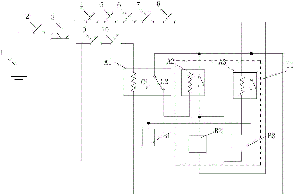
[0016] refer to figure 1 , figure 2 , this embodiment includes leading out the positive pole line and the negative pole line on the battery 1 of the automobile, the ignition switch 2 is connected in series on the positive pole line, and the wiper branch circuit and the water spray pump branch circuit are connected in parallel between the positive pole line and the negative pole line after the ignition switch 2 1. Spray cooling branch; the wiper switch 9, the wiper low water level switch 10, and the double-throw relay A1 coil circuit are connected in series on the wiper branch; the water spray pump B1 and the double-throw relay A1 output circuit are connected in series on the water spray pump branch The normally open contact C1 in the middle; the AC switch 4, the low pressure switch 5, the spray low water level switch 6, the high pressure switch 7, the high water level switch 8, and the water spray pump control module 11 are connected in series on the spray cooling branch. Th...
Embodiment 2
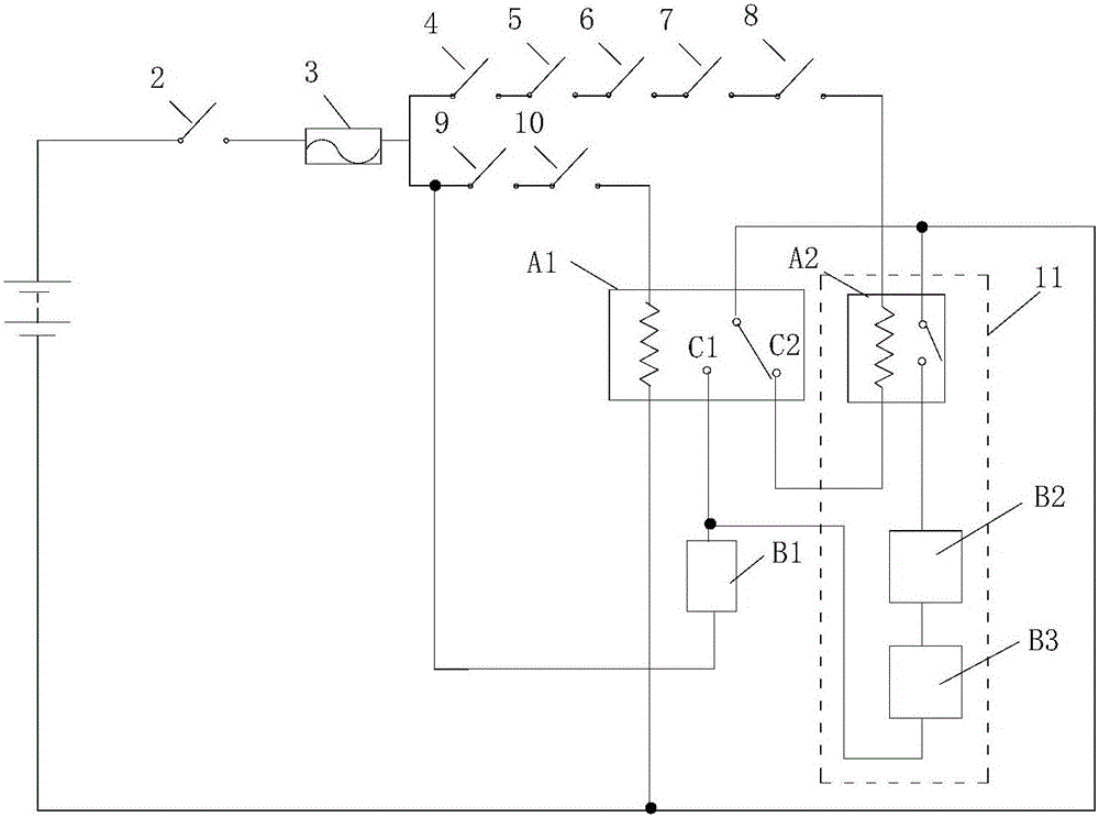
[0019] refer to image 3, this embodiment is basically the same as Embodiment 1, except that the water spray pump control module 11 includes a delay relay (A2), a wiper normally-on solenoid valve (B2), a spray normally-off solenoid valve (B3), The coil branch of the delay relay (A2), the normally closed contact (C2) in the output circuit of the double-throw relay (A1) are connected in series on the spray cooling branch, and the output circuit of the delay relay (A2) is connected in series The wiper normally-on solenoid valve (B2) and the spray normally-off solenoid valve (B3) form a module branch. The positive pole of the module branch is connected in parallel to the water spray pump branch. The negative pole of the module branch is connected to the negative pole of the battery 1. Wire.
PUM
 Abstract
Description
Claims
Application Information
PatSnap Eureka turns technology decisions into work you can execute. Powered by our Innovation Knowledge Graph, it runs expert workflows across engineering, life sciences, materials and intellectual property. Get your review-ready output in minutes.


