Annealing furnace

An annealing furnace and annealing technology, applied in the direction of furnaces, furnace types, heat treatment furnaces, etc., can solve the problems of inconvenient removal of gas cylinders, poor annealing treatment effect, uniform heating of the surface of gas cylinders, etc., and achieve high temperature uniformity and improved Quality and work efficiency improvement effect

Inactive Publication Date: 2015-11-18
SINOMA SCI & TECH CHENGDU CO LTD
View PDF5 Cites 9 Cited by
  • Summary
  • Abstract
  • Description
  • Claims
  • Application Information

AI Technical Summary

Problems solved by technology

[0003] The existing gas cylinders are annealed in the annealing furnace, and the surface of the gas cylinder cannot be heated evenly, resulting in poor annealing effect; in addition, it is very inconvenient to take out the gas cylinder after annealing

Method used


Image

  • Annealing furnace

Examples


Embodiment Construction

[0017] The present invention will be described in further detail below through specific implementation examples and in conjunction with the accompanying drawings.

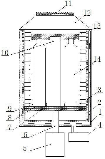
[0018] figure 1 Shown is an annealing furnace provided by the present invention, including: furnace body 1, annealing shell 2, through hole 3, hot air blower 4, cylinder 5, cylinder output shaft 6, support plate 7, insulation layer 8, fixing groove 9. Fixed column 10, gas purification chamber 11, furnace cover 12, fixed plate 13, temperature sensor and controller. The furnace body 1 is provided with an annealing shell 2, and a gap is provided between the bottom surface and the circumferential surface of the annealing shell 2 and the furnace body 1, and the upper end of the annealing shell 2 is fixedly connected with the furnace body 1; the annealing shell 2. The circumferential surface of the middle and upper part is covered with through holes 3. The lower part of the annealing shell 2 is provided with a support p...


PUM


Abstract

The invention discloses an annealing furnace. The furnace comprises a furnace body. An annealing shell body is arranged in the furnace body. Gaps are arranged between the furnace body and the bottom surface of the annealing shell body as well as between the circumference surface of the annealing shell body. The upper end of the annealing shell body is fixedly connected with the furnace body. The circumference surface on the middle-upper portion of the annealing shell body is besprinkled with through holes. The inner lower portion of the annealing shell body is provided with a support plate. A thermal insulation layer is arranged on the support plate. The thermal insulation layer is provided with a fixed pillar and a plurality of fixed grooves. A fixed plate is detachably arranged at the top end of the fixed pillar. A plurality of grooves are formed in the positions, corresponding to the fixed grooves, of the fixed plate and are matched with gas cylinder openings. A furnace lid is arranged at the top end of the furnace body and provided with a gas purification cavity. An air cylinder is arranged at the lower end of the furnace body. An air cylinder output shaft extends into the furnace body and is connected with the support plate. An air heater is arranged at the lower end of the furnace body and communicated with the gap between the bottom surface of the annealing shell body and the furnace body. The annealing furnace is capable of improving the working efficiency.

Description

technical field [0001] The invention relates to the technical field of metal annealing, in particular to an annealing furnace. Background technique [0002] Annealing refers to slowly heating a metal to a certain temperature, holding it for a sufficient time, and then cooling it at an appropriate rate. The purpose is to reduce hardness, improve machinability; eliminate residual stress, stabilize size, reduce deformation and crack tendency; refine grain, adjust structure, and eliminate structure defects. The annealing of gas cylinders is to eliminate internal stress and achieve good plasticity. The annealing furnace is a machine used to implement the annealing process. [0003] The existing gas cylinders are annealed in the annealing furnace, and the surface of the gas cylinder cannot be heated uniformly, resulting in poor annealing effect; in addition, it is very inconvenient to take out the gas cylinder after the annealing is completed. Contents of the invention [000...

Claims


Application Information

Patent Timeline
Patent Type & Authority Applications(China)
IPC IPC(8): C21D1/26C21D9/00
Inventor 冯存江李红梅王健
Owner SINOMA SCI & TECH CHENGDU CO LTD
Why Eureka
Try Eureka