Eureka AIR delivers breakthrough ideas for toughest innovation challenges, trusted by R&D personnel around the world.

Magnetic mask plate for vapor deposition

A mask plate and mask technology, which is applied in the directions of vacuum evaporation plating, sputtering plating, ion implantation plating, etc., can solve the problems of support bar deformation, interference, and fracture of the opening of the organic mask layer, so as to achieve easy fabrication, Effects that are not easily damaged

Inactive Publication Date: 2015-11-18
KUN SHAN POWER STENCIL
View PDF6 Cites 11 Cited by
  • Summary
  • Abstract
  • Description
  • Claims
  • Application Information

AI Technical Summary

Problems solved by technology

[0005] Chinese patent 2012204544970 discloses a technical solution in which a composite mask is composed of an organic mask layer and a mask support layer. However, in the actual manufacturing process of the mask, since the mask support layer in this technical solution contains a large number Smaller support bars (all on the order of tens of μm), the smaller support bars are easily deformed (or broken) and interfere with the opening of the organic mask layer, and even cause the mask to be scrapped

Method used


Image

  • Magnetic mask plate for vapor deposition
  • Magnetic mask plate for vapor deposition
  • Magnetic mask plate for vapor deposition

Examples


Embodiment Construction

[0036] Embodiments of the present invention are described in detail below, examples of which are shown in the drawings, wherein the same or similar reference numerals designate the same or similar elements or elements having the same or similar functions throughout. The embodiments described below by referring to the figures are exemplary only for explaining the present invention and should not be construed as limiting the present invention.

[0037] In describing the present invention, it should be understood that the terms "upper", "lower", "bottom", "top", "front", "rear", "inner", "outer", "horizontal", " The orientation or positional relationship indicated by "vertical", etc. is based on the orientation or positional relationship shown in the drawings, which is only for the convenience of describing the present invention and simplifying the description, rather than indicating or implying that the device or element referred to must have a specific orientation, so as to Spe...


PUM

PropertyMeasurementUnit
thicknessaaaaaaaaaa
thicknessaaaaaaaaaa
thicknessaaaaaaaaaa

Abstract

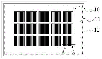
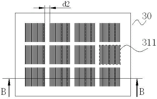
The invention provides a magnetic mask plate for vapor deposition. The magnetic mask plate for vapor deposition is composed of a mask layer and a mask supporting layer. The mask layer is made of organic materials. The mask supporting layer is made of metal materials. Due to the fact that the mask layer and the mask supporting layer which form the mask plate have special matched structures, the magnetic mask plate for vapor deposition can well meet the requirement for forming organic materials on a substrate in the OLED vapor deposition application process.

Description

technical field [0001] The invention belongs to the display panel industry, and relates to a tool used in the middle link of OLED display panel production, in particular to a magnetic mask used for evaporation of organic light-emitting materials on the OLED display panel. Background technique [0002] Because organic light-emitting diodes (Organic Light-Emitting Diode, OLED) have both self-illumination, no backlight, high contrast, thin thickness, wide viewing angle, fast response, can be used for flexible panels, wide operating temperature range, structure and The excellent characteristics such as relatively simple manufacturing process are considered to be the emerging application technology of the next generation of flat panel displays. [0003] The most important part in the OLED production process is to apply the organic layer to the substrate according to the requirements of the drive matrix to form a key light-emitting display unit. OLED is a solid material, and th...

Claims


Application Information

Patent Timeline
Patent Type & Authority Applications(China)
IPC IPC(8): C23C14/04C23C14/24
Inventor 魏志凌潘世珎张炜平杨涛
Owner KUN SHAN POWER STENCIL
Why Eureka
Eureka Blog
Learn More