Device and method for conveying concrete on water surface of wide river

A concrete and river technology, applied in the erection/assembly of bridges, construction material processing, bridges, etc., can solve the problems of low construction efficiency, waste of construction period, waste of resources, etc., to improve construction quality, short conveying distance, and speed up construction progress. Effect

Inactive Publication Date: 2015-11-18
CHINA 19TH METALLURGICAL CORP
View PDF9 Cites 3 Cited by
  • Summary
  • Abstract
  • Description
  • Claims
  • Application Information

AI Technical Summary

Problems solved by technology

[0003] Since the main pier cap of the bridge is a reinforced concrete structure, its size is large, and the demand for concrete is large. In order to improve work efficiency and design and construction considerations, the main pier caps on both sides of the river are often constructed at the same time. For safety, Considering environmental protection, taking into account the different topographical structures on both sides of the river, the concrete mixing site and concrete tank trucks will only be installed on one side of the river. Every day there is a demand for concrete on both sides of the river. At this time, the concrete tank trucks need to detour along the river. Concrete transportation, because there is no bridge near the river or the load capacity of the bridge is limited, the concrete tanker needs to detour along the river for a long distance to achieve the purpose of conveying concrete to the opposite bank. The construction efficiency is very low, resulting in a waste of construction time and a lot of resources. A more ideal device and method for conveying concrete along the water surface of a wide river

Method used


Image

  • Device and method for conveying concrete on water surface of wide river
  • Device and method for conveying concrete on water surface of wide river
  • Device and method for conveying concrete on water surface of wide river

Examples


Embodiment Construction

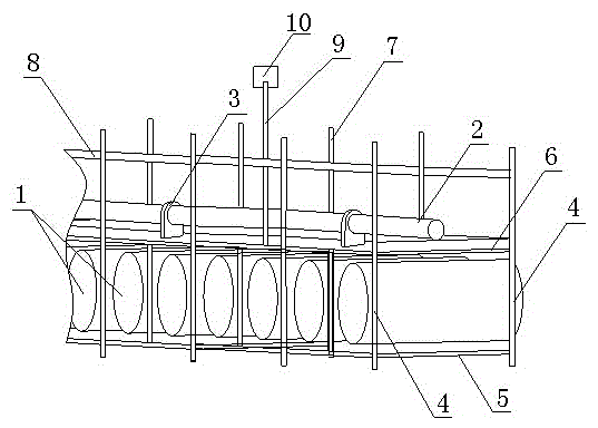
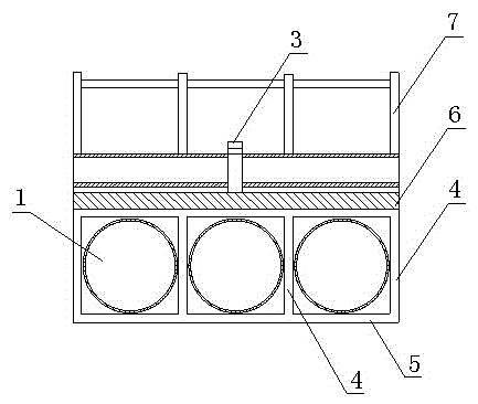
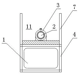
[0025] like figure 1 , 2 , 3, the present invention is a device for conveying concrete on the water surface of a wide river channel, which is characterized in that it comprises a concrete conveying platform formed by arranging a plurality of cylindrical buoyancy barrels 1 with the same shape and size in sequence, and the concrete conveying platform It includes several platform units 11, each platform unit 11 includes a buoyancy support, and the buoyancy support includes four vertical beams 4, four beams 6 on the top surface and four beams 5 on the bottom surface. A cylindrical buoyancy barrel 1 is arranged in the support frame of the buoyancy support, and four beams 6 on the top surface of the buoyancy support form the platform working surface, and the four vertical beams 4 of the buoyancy support extend upward to form the measuring beam 7 of the platform working surface , the different platform conveying units are connected end to end to form a concrete conveying platform, a...


PUM


Abstract

The invention discloses a device and method for conveying concrete on the water surface of a wide river. The device comprises a concrete conveying platform, which is formed by arranging a plurality of cylindrical buoyancy cans with same shapes and sizes in parallel in sequence, wherein the concrete conveying platform comprises a plurality of platform units; each platform unit comprises a buoyancy bracket; each buoyancy bracket comprises a cuboid-shaped bracket frame, which is formed by welding four vertical beams, four cross beams on the top surface and four cross beams on the bottom surface; a cylindrical buoyancy can is arranged in each bracket frame; the four cross beams on the top surface of each buoyancy bracket form a platform working surface; the four vertical beams of each buoyancy bracket extend upwards to form a side beam of the platform working surface; the different platform conveying units are end to end to form the concrete conveying platform; and concrete conveying steel pipes are arranged on the platform working surfaces. According to the device and method for conveying the concrete on the water surface of the wide river, disclosed by the invention, as the concrete is conveyed by means of the water surface of the wide river, the concrete conveying safety is guaranteed, the construction progress is accelerated, the construction quality is improved and the construction cost is reduced.

Description

technical field [0001] The invention relates to a device for transporting concrete on the water surface of a wide river channel, in particular to a device and method for transporting concrete across the water surface of a wide river channel to the opposite bank of the channel. Background technique [0002] In the construction and construction of large-scale bridges in the field, it is often encountered in the construction of large-scale bridges and approach roads across rivers and rivers. The large-scale bridges have many main piers, and different main pier caps will be built in different positions. Different geographical locations, topographic features and geological structures. For example, in the construction of the main pier caps of bridges across rivers and rivers, some of the main pier caps will be built on the gentle slope riverbed across the river and river, some of the main pier caps will be built on the side of the river, and some of the main pier caps will be buil...

Claims


Application Information

Patent Timeline
IPC IPC(8): E01D21/00E04G21/02
Inventor 刘平许明君陈德华
Owner CHINA 19TH METALLURGICAL CORP
Why Eureka
Try Eureka