
A kind of oil recovery method that nitrogen foam inhibits edge water propulsion in thermal recovery of heavy oil

A thermal recovery of heavy oil, nitrogen foam technology, applied in the direction of production fluid, earth drilling, wellbore/well components, etc., can solve the problems of small steam sweep range, low oil recovery efficiency, edge water intrusion, etc., and achieve the expansion of steam sweep range, increase oil recovery efficiency, and improve efficiency

Active Publication Date: 2019-04-05
CHINA PETROLEUM & CHEM CORP +1
View PDF7 Cites 2 Cited by
  • Summary
  • Abstract
  • Description
  • Claims
  • Application Information

AI Technical Summary

Problems solved by technology

[0004] The purpose of the present invention is to provide an oil recovery method in which nitrogen foam suppresses edge water propulsion in heavy oil thermal recovery, and solves the problems of severe edge water intrusion, small steam sweep range, and low oil recovery efficiency when steam huff and puff is used for heavy oil thermal recovery.

Method used

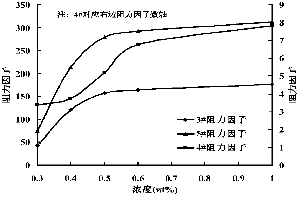
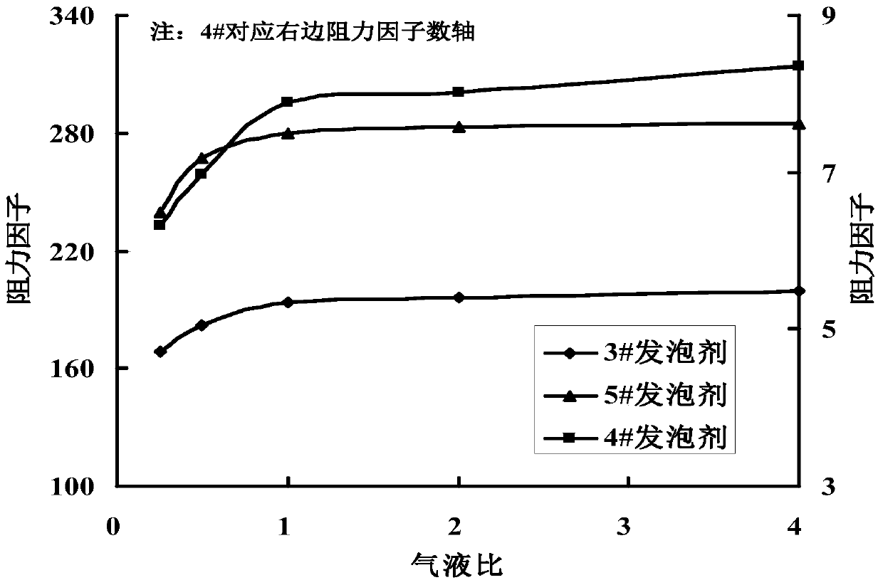
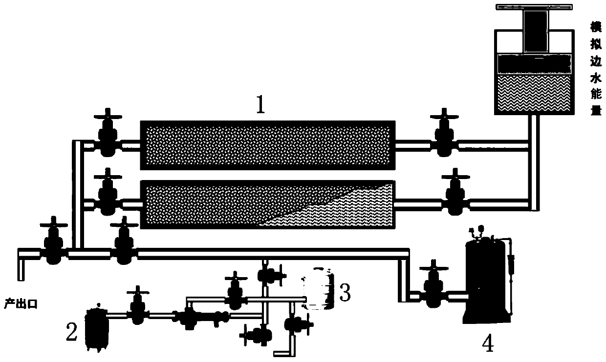

Image

  • A kind of oil recovery method that nitrogen foam inhibits edge water propulsion in thermal recovery of heavy oil
  • A kind of oil recovery method that nitrogen foam inhibits edge water propulsion in thermal recovery of heavy oil
  • A kind of oil recovery method that nitrogen foam inhibits edge water propulsion in thermal recovery of heavy oil

Examples


Embodiment 1

[0025] The oil production method in which nitrogen foam suppresses edge water propulsion in thermal recovery of heavy oil in this embodiment comprises the following steps:

[0026] 1) When the periodical comprehensive water content of the oil production well is 95%, nitrogen is injected to form a pre-nitrogen slug before steam injection in the oil production well, and the injection amount of the pre-nitrogen is 1 / 3 of the total nitrogen design injection amount, and the total nitrogen design The injection volume is 40 times of the high-temperature steam design injection volume;

[0027] 2) Inject foaming liquid into the oil production well, the mass percentage of the foaming agent in the foaming liquid is 0.5%, the foaming liquid is contacted with the pre-nitrogen to foam, and the gas-liquid ratio is 1:1;

[0028] 3) Inject nitrogen gas into the production well to form a central nitrogen slug, and the injection rate of the central nitrogen gas is 2 / 3 of the total nitrogen desig...

Embodiment 2

[0032] The oil production method in which nitrogen foam suppresses edge water propulsion in thermal recovery of heavy oil in this embodiment comprises the following steps:

[0033] 1) Before the steam injection in the production well, when the comprehensive water content of the production well is 92%, nitrogen is injected to form a pre-nitrogen slug, and the pre-nitrogen injection amount is 1 / 2 of the total nitrogen design injection amount The injection volume is 60 times of the high-temperature steam design injection volume;

[0034] 2) Inject foaming liquid into the oil production well, the mass percentage of the foaming agent in the foaming liquid is 0.4%, the foaming liquid is contacted with the front nitrogen to foam, and the gas-liquid ratio is 1.5:1;

[0035] 3) Inject nitrogen gas into the oil production well to form a central nitrogen slug, and the injection rate of the central nitrogen gas is 1 / 2 of the total nitrogen design injection rate;

[0036] 4) Inject a desi...

Embodiment 3

[0039] The oil production method in which nitrogen foam suppresses edge water propulsion in thermal recovery of heavy oil in this embodiment comprises the following steps:

[0040] 1) Before steam injection in oil production wells, when the periodic comprehensive water content of oil production wells is 90%, nitrogen is injected to form a pre-nitrogen slug, and the injection amount of pre-nitrogen is 1 / 3 of the total nitrogen design injection amount. The injection volume is 80 times of the high-temperature steam design injection volume;

[0041] 2) Inject foaming liquid into the oil production well, the mass percentage of the foaming agent in the foaming liquid is 0.6%, the foaming liquid is contacted with the front nitrogen to foam, and the gas-liquid ratio is 2:1;

[0042] 3) Inject nitrogen gas into the production well to form a central nitrogen slug, and the injection rate of the central nitrogen gas is 2 / 3 of the total nitrogen design injection rate;

[0043] 4) Inject a...


PUM


Abstract

The invention discloses an oil recovery method for restraining thickened oil thermal recovery edge water propulsion by means of nitrogen foam. The oil recovery method comprises that 1) before steam is injected into an oil recovery well, and nitrogen is injected to form a preposed nitrogen section plug; 2) foaming liquid is injected into the oil recovery well, and the foaming liquid is contacted with the preposed nitrogen to foam; 3) nitrogen is injected into the oil recovery well to form a mid-arranged nitrogen section plug; and 4) steam is injected into the oil recovery well. In the oil recovery method for restraining thickened oil thermal recovery edge water propulsion by means of nitrogen foam, processes of preposing nitrogen section plug, injecting foaming agent, mid-arranging nitrogen section plug and injecting steam are carried out sequentially, the preposed nitrogen section plug pushes edge water to a deep part of the oil reservoir, the foaming liquid is fully contacted with the preposed nitrogen to foam the mid-arranged nitrogen section plug pushes the foaming agent to a deep part of the oil reservoir, and separates the foaming agent from high-temperature steam, and the foaming agent is prevented from being degraded at a high temperature. The oil recovery method is used for thickened oil field thermal recovery steam huff-puff wells, the propulsion of edge water can be effectively restrained, the spread range of steam is increased, the oil recovery efficiency is improved, and the oil recovery method is suitable for popularization and application.

Description

technical field [0001] The invention belongs to the technical field of heavy oil thermal recovery, and in particular relates to an oil recovery method in which nitrogen foam suppresses edge water propulsion in heavy oil thermal recovery. Background technique [0002] Heavy oil is also called heavy crude oil or high viscosity crude oil, usually refers to d 4 20 >0.92 crude oil. In heavy oil, the content of straight-chain waxy hydrocarbon light fractions is low, but the content of colloid and asphaltenes is high, and the content of elemental compounds such as sulfur, oxygen, nitrogen, and metals such as nickel and vanadium is also high, so heavy oil has a large specificity, With high viscosity and low freezing point, it generally exhibits Newtonian fluid characteristics in a wide temperature range. Under the condition of formation temperature, heavy oil has high viscosity and is difficult to flow in the original formation. There are great difficulties in ordinary mining,...

Claims


Application Information

Patent Timeline
IPC IPC(8): E21B43/16E21B43/22E21B43/24
Inventor 刘继伟郝立军李德儒王若浩蔡汉文白长琦李元钦冯晓青白新潮刘书晓关键
Owner CHINA PETROLEUM & CHEM CORP
Learn More