
A shield machine mud water circulation and stone crushing system

A shield machine and stone crushing technology, which is applied in grain processing, mining equipment, earth drilling and mining, etc., can solve the problems of low crushing capacity, crushing of large-sized pebbles, and damage to the slurry pump, and the damage of the slurry pump to achieve crushing capacity. Strong, safe and reliable maintenance steps, good maintainability

Active Publication Date: 2018-02-09
CHINA RAILWAY CONSTR HEAVY IND
View PDF7 Cites 2 Cited by
  • Summary
  • Abstract
  • Description
  • Claims
  • Application Information

AI Technical Summary

Problems solved by technology

When the shield machine is constructing tunnels in the water-rich strata with high content, high hardness, and large particle size pebbles in southwest, northwest, and north China, the crushing speed of the hydraulic jaw crusher in the air cushion cabin is only four per minute. times, and often damaged under harsh working conditions, it is impossible to quickly crush the pebbles with large flow and large particle size in the air cushion cabin to the conveying range of the slurry pump, and it is very easy for the shield machine to have pebbles in the air cushion cabin and muddy water Faults such as the blockage of the slurry outlet pipeline of the circulation system and the damage of the slurry discharge pump caused the shield machine to be shut down for maintenance for a long time, which greatly limited its excavation ability.
[0003] Therefore, this field needs to develop a kind of new shield machine mud-water circulation and crushing system to overcome the problem that the crushing capacity of the hydraulic jaw crusher in the above-mentioned air cushion cabin is too low

Method used


Image

  • A shield machine mud water circulation and stone crushing system
  • A shield machine mud water circulation and stone crushing system
  • A shield machine mud water circulation and stone crushing system

Examples


Embodiment Construction

[0052] The specific embodiments of the present invention will be briefly described below in conjunction with the accompanying drawings of the specification.

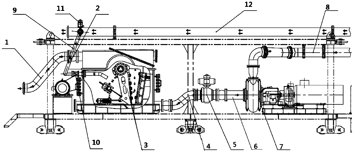
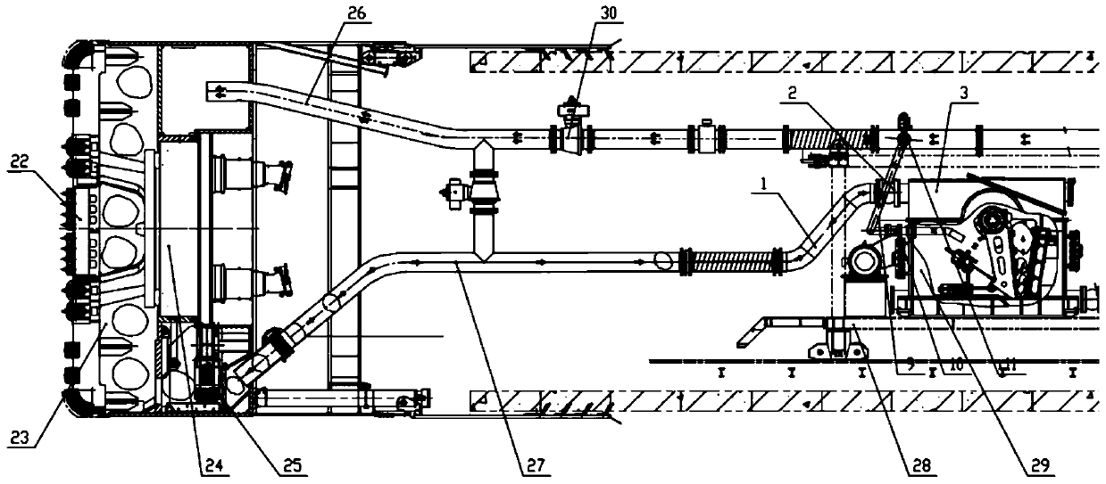
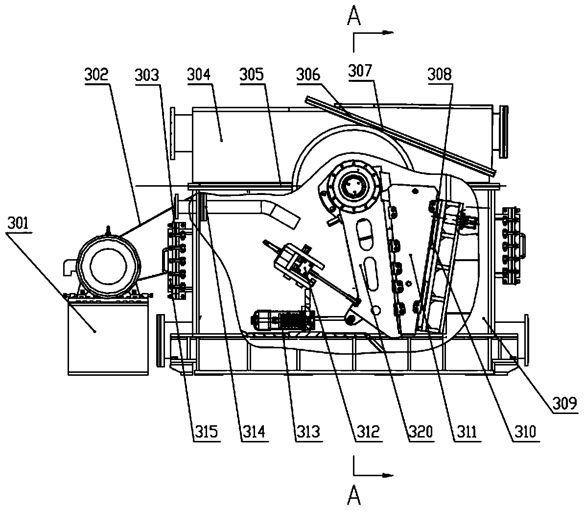
[0053] Such as figure 1 As shown, the mud-water circulation and rock crushing system provided by the present invention includes a shield machine mud pipeline crushing system 29. The shield machine mud pipeline crushing system includes a slurry elbow 1, a large shock absorbing throat 2, Mud pipeline crusher 3, slurry discharge elbow 2 4, large hydraulic ball valve 5, slurry discharge straight pipe 6, slurry pump 7, slurry discharge elbow 3 8, flushing pipe 9, small shock absorbing throat 10, small liquid Moving ball valve 11, crusher slurry inlet branch pipe 12. The working principle of the mud pipeline crushing system of the shield machine of the present invention is: the left end of the mud pipeline crusher 3, which has the function of sealing high-pressure mud and crushing large-size pebble, is connected to the mud discha...


PUM


Abstract

The invention provides a mud-water circulation and gravel system of a shield machine, which includes a slurry inlet pipe, an air cushion cabin, a discharge pipe, a mud pipeline crusher, a slurry discharge pump and a slurry discharge pipe connected in series through pipelines; The pipe is used to transport the mud and gravel in the air cushion cabin to the mud pipeline breaker, and the mud pipeline breaker breaks the stones from the air cushion cabin; and the mud pipeline breaker contains a sealed A closed jaw crusher with a pad, a frame and a movable jaw assembly, and the inside of which can seal the mud fluid with a pressure above 0.5MPa. The crusher in the system provided by the present invention has greater crushing capacity than the hydraulic jaw crusher in the air cushion cabin of the shield machine, has a long service life and high reliability, and solves the problem of stagnation in the water-rich sand and pebbles of the existing shield machine. Discharge, blockage and other issues. And it is installed on a trailer, which reduces the number of repairs of the press-in cabin by personnel, reduces the use cost and construction risk of the shield machine, and improves the geological adaptability and tunneling efficiency of the shield machine.

Description

Technical field [0001] The invention belongs to the technical field of tunneling machinery, and specifically relates to a shield machine mud water circulation and mud pipeline crushing system. Background technique [0002] The shield machine includes an excavation cabin with a cutter head, an air cushion cabin and a trailer from the front end to the rear end of the tunneling position. The main purpose of the air cushion cabin is to balance and stabilize the excavation surface. At present, when the shield machine adopts the mud-water balance method to excavate the tunnel in the water-rich sand and pebble formation, it is necessary to discharge the ballast through the mud-water circulation system and maintain the stability of the excavation surface; at this time, the shield machine's ballast discharge method is: knife The ballast soil, pebbles and the mud injected outside the tunnel are mixed in the excavation cabin to form a fluid that enters the air-cushion cabin from the mud doo...

Claims


Application Information

Patent Timeline
Patent Type & Authority Patents(China)
IPC IPC(8): E21D9/06B02C1/04
Inventor 刘飞香程永亮张社军麻成标容锦任锦江范瑞强文中保彭帅全雪勇
Owner CHINA RAILWAY CONSTR HEAVY IND
Learn More