Internal combustion engine cylinder anti-eccentric wear device

An internal combustion engine cylinder and anti-eccentric wear technology, which is applied in the direction of cylinders, cylinder heads, mechanical equipment, etc., can solve the problems of reduced heat energy utilization rate of internal combustion engines, damage to the inner wall of the cylinder or piston, and uneven friction, so as to eliminate the phenomenon of partial wear , easy processing, and the effect of reducing operating costs

Active Publication Date: 2018-03-13
武克学
View PDF11 Cites 0 Cited by
  • Summary
  • Abstract
  • Description
  • Claims
  • Application Information

AI Technical Summary

Problems solved by technology

[0002] At present, the piston in the cylinder of the internal combustion engine moves in a straight line in the cylinder, but the power provided by the linear motion of the piston drives the special structure of the crankshaft and connecting rod to run, and the direction of the thrust or pulling force generated by the piston when it moves to the crankshaft and connecting rod is constantly changing. That is to say, the direction of the thrust or pull force of the piston on the crankshaft connecting rod is not kept on the same line as the direction of the piston movement, so the friction force generated by the piston on the cylinder wall when it is running in the cylinder is uneven, so After the piston moves at a high speed for a long time in the cylinder, it is easy to cause eccentric wear, which will damage the inner wall of the cylinder or the piston and cause air leakage, resulting in a decrease in the utilization rate of heat energy of the internal combustion engine. This is a problem that has not been solved since the use of the internal combustion engine.
In addition, the piston also plays a guiding role in the movement of the cylinder. In order to prevent the eccentric wear of the cylinder, the length of the piston is appropriately increased. However, increasing the length of the piston increases the weight of the piston, which will inevitably lead to the consumption of the piston itself. more energy resulting in waste of fuel

Method used


Image

  • Internal combustion engine cylinder anti-eccentric wear device
  • Internal combustion engine cylinder anti-eccentric wear device
  • Internal combustion engine cylinder anti-eccentric wear device

Examples


Embodiment Construction

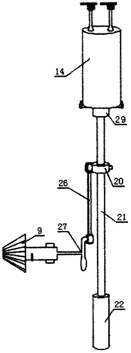
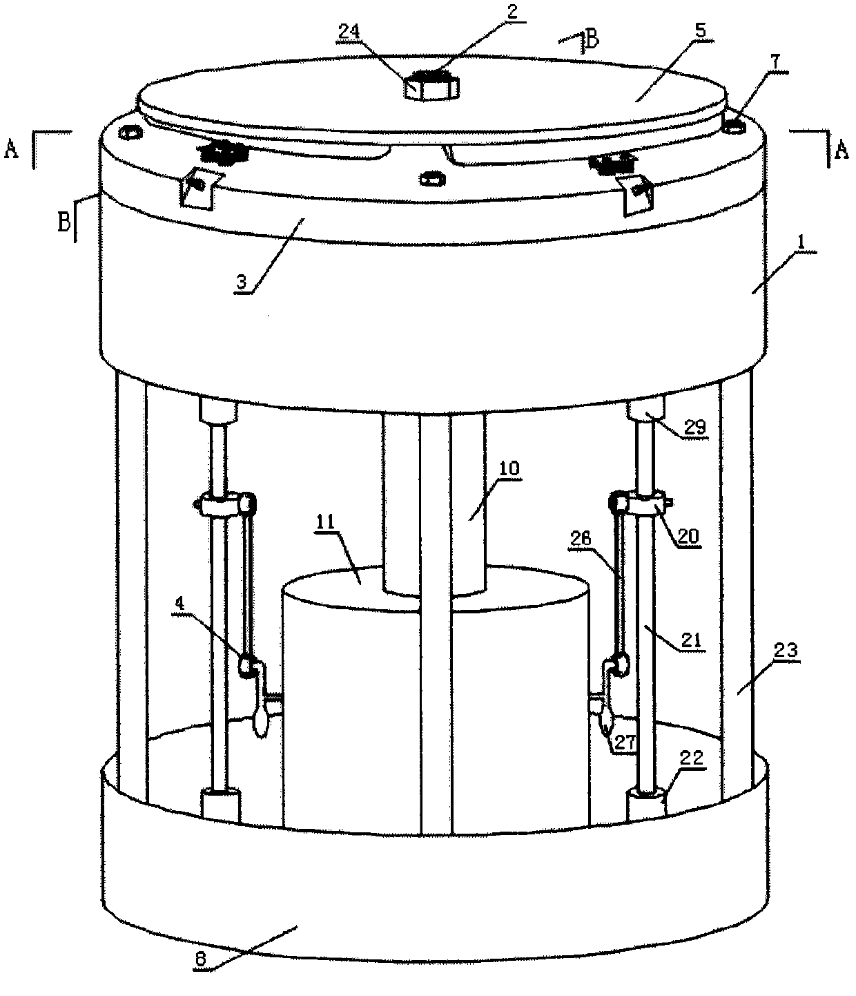
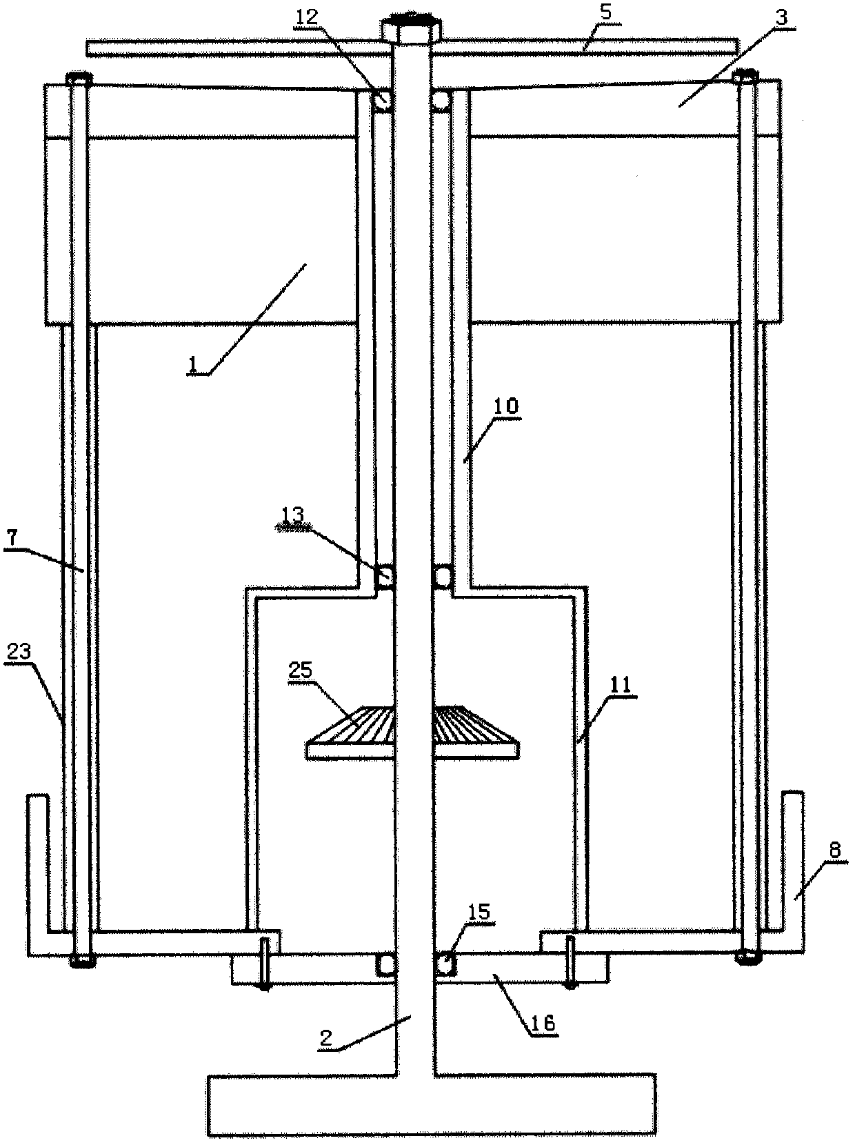
[0016] Such as figure 1 , figure 2 , image 3 and Figure 4 As shown, the eccentric wear prevention device for the cylinder of an internal combustion engine of this embodiment includes a cylinder block 1, an output power shaft 2, a cylinder head 3, a crankshaft connecting rod device 4, a cam disc 5, and a lubricating device 6, and the cylinder block 1 is provided The cylinder bore 18 and the piston 28, the crankshaft connecting rod device 4 includes a crankshaft 27, a connecting rod 26 and a crankshaft gear 9, and the lubricating device 6 is provided with a lubricating oil tank 8 bottom plate. The internal combustion engine cylinder anti-eccentric wear device is provided with an upper sleeve 29, a lower sleeve 22 and a piston guide rod 21. The upper sleeve 29 is fixed to the lower end of the cylinder bore 18 of the cylinder block 1, and the lower sleeve 22 is fixed to the inner bottom of the lubricating oil tank 8. , The two ends of the piston guide rod 21 are respectively slee...


PUM


Abstract

The invention discloses an anti-eccentric wearing device for a cylinder of an internal combustion engine and relates to the field of the internal combustion engine. The anti-eccentric wearing device solves the problems of high processing difficulty, easy wearing, high energy consumption and the like existing in the internal combustion engine at present. Upper shaft sleeves of the anti-eccentric wearing device for the cylinder of the internal combustion engine are fixed at the lower ends of cylinder holes of a cylinder block, and lower shaft sleeves of the anti-eccentric wearing device are fixed at the inner bottom of a lubricating oil tank; two ends of each piston guide rod are respectively connected to the corresponding upper shaft sleeve and the corresponding lower shaft sleeve in a sleeved manner; each connecting rod is connected to the corresponding piston guide rod through a piston guide rod retaining latch sleeve; the piston guide rod retaining latch sleeves and the piston guide rods are fixed by pin bolts; and the upper ends of the piston guide rods and pistons are fixed. The anti-eccentric wearing device is simple in structure, easy to process, and convenient to install, is energy-saving, and can greatly prolong the service life of the cylinder and the piston.

Description

Technical field [0001] The invention relates to the field of internal combustion engines, in particular to an anti-eccentric wear device for cylinders of internal combustion engines. Background technique [0002] At present, the piston in the cylinder of an internal combustion engine moves linearly in the cylinder, but the power provided by the linear motion of the piston pushes the crankshaft connecting rod to operate with a special structure, and the direction of thrust or pulling force generated by the piston on the crankshaft connecting rod changes constantly That is to say, the direction of the thrust or pulling force of the piston on the crankshaft connecting rod is not kept in the same straight line with the direction of piston movement. Therefore, the friction force generated by the piston on the cylinder wall is not uniform when the piston is running in the cylinder. After the piston moves at a high speed for a long time in the cylinder, it is easy to cause eccentric wea...

Claims


Application Information

Patent Timeline
Patent Type & Authority Patents(China)
IPC IPC(8): F02F1/00F02B75/32
Inventor 武克学武成阁
Owner 武克学
Why Eureka
Try Eureka