Thermally driven pulse tube refrigerator system

A technology of pulse tube refrigerator and thermal drive, which is applied in refrigerators, refrigeration and liquefaction, compressors, etc., can solve the problems of increasing system complexity, reducing reliability, and large casing vibration, so as to reduce system complexity, Improve reliability, reduce process difficulty and effect

Active Publication Date: 2015-11-18
TECHNICAL INST OF PHYSICS & CHEMISTRY - CHINESE ACAD OF SCI
View PDF5 Cites 37 Cited by
  • Summary
  • Abstract
  • Description
  • Claims
  • Application Information

AI Technical Summary

Problems solved by technology

[0004] However, there is a mechanical moving part in the free-piston Stirling refrigerator of the heat-driven cryogenic refrigerator system—the displacer. This moving part has high requirements on the process, and it is necessary to ensure a good gap sealing effect and a small mechanical damping , at the same time, the existence of the moving parts will also generate a large vibration of the casing. Although the application proposes to reduce the vibration caused by the ejector through the opposite arrangement, this structure also increases the complexity of the system and reduces the reliability. sex

Method used


Image

  • Thermally driven pulse tube refrigerator system
  • Thermally driven pulse tube refrigerator system
  • Thermally driven pulse tube refrigerator system

Examples


Embodiment 1

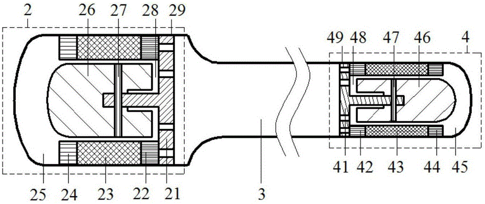
[0042] Figure 4 It is a structural schematic diagram of the heat-driven pulse tube refrigerator system (Embodiment 1) of the present invention. like Figure 4 As shown, the free-piston Stirling engine 2, the acoustic resonance tube 3 and the pulse tube refrigerator 1 of the heat-driven pulse tube refrigerator system of the present embodiment are all one; the acoustic resonance tube 3 is a pipeline of equal or reduced diameter, The free-piston Stirling engine 2 and the pulse tube refrigerator 1 are respectively connected to both sides of the acoustic resonance tube 3;

[0043] The free piston Stirling engine 2 includes:

[0044] The engine block 29 communicated with one side of the acoustic resonance tube 3;

[0045] Be fixed on the engine fixed base 21 near the side of the acoustic resonance tube 3 in the engine block 29;

[0046] The engine annular heat release end heat exchanger 22, the engine annular heat regenerator 23 and the engine annular heat absorption end heat e...

Embodiment 2

[0075] Figure 5 It is a structural schematic diagram of a heat-driven pulse tube refrigerator system according to Embodiment 2 of the present invention; Figure 5 It can be seen that the heat-driven pulse tube refrigerator system of this embodiment is composed of two free-piston Stirling engines 2 and one pulse tube refrigerator 1 located on both sides of the acoustic resonance tube 3; the two free-piston Stirling engines 2 are Arranged oppositely; the engine fixed base 21 of the two free-piston Stirling engines 2 and the acoustic resonance tube 3 are connected by a three-way tube.

[0076]The working principle of embodiment 2 is the same as that of embodiment 1, the difference is that there are two free-piston Stirling engines in embodiment 2, and the structural parameters are exactly the same, and they are arranged oppositely; as Figure 5 As shown, two free-piston Stirling engines 2 are on the same axis, and the engine fixed base 21 is connected by a tee pipe. This arrang...

Embodiment 3

[0078] Image 6 It is a structural schematic diagram of the coupled opposed arrangement of the heat-driven pulse tube refrigerator system in Embodiment 3 of the present invention; as Image 6 As shown, the two pulse tube refrigerators 1 and the acoustic resonance tube 3 are independent, while the two free-piston Stirling engines 2 share the same expansion chamber, and the coupled opposed arrangement system is symmetrically arranged along the axial direction.

[0079] The working principle of embodiment 3 is the same as that of embodiment 1, the difference is that embodiment 3 adopts two sets of systems with identical structural parameters arranged symmetrically along the axial direction; as Image 6 As shown, the engines of the two systems share the same engine expansion chamber, which can make the motion phase difference of the two engine ejectors 180°, thereby completely canceling the body vibration of the two systems. Compared with embodiment 1, embodiment 3 has less vibra...


PUM


Abstract

The invention discloses a thermally driven pulse tube refrigerator system which comprises one or two free piston stirling engines, one or two pulse tube refrigerators and one or two acoustic resonance tubes, wherein each acoustic resonance tube is a first-class diameter or variable diameter pipe; each free piston stirling engine and each pulse tube refrigerator are respectively connected to two sides of each acoustic resonance tube; acoustic power generated by the free piston stirling engines is transmitted to the pulse tube refrigerators through the acoustic resonance tubes; the pulse tube refrigerators generate the refrigerating effect; the acoustic resonance tubes not only can play an acoustic power transmission role, but also can play an acoustic field phase modulation role; the acoustic fields in thermo-acoustic and acoustic-cold conversion core components, namely refrigerator regenerators, of the thermally driven pulse tube refrigerator are traveling wave phases; the thermal efficiency is high; meanwhile, no mechanical motion component is arranged in the pulse tube refrigerator; the thermally driven pulse tube refrigerator system has low vibration and high reliability; the refrigerating capacity from hectowatts to kilowatts or even higher can be obtained within a temperature region of 60-150K.

Description

technical field [0001] The invention relates to the field of thermal power systems, in particular to a heat-driven pulse tube refrigerator system. Background technique [0002] With the enhancement of human awareness of environmental protection and sustainable development, the proportion of clean energy such as natural gas, coal bed methane and shale gas in the primary energy structure continues to increase. However, compared with traditional energy sources such as coal and oil, natural gas, coalbed methane and shale gas are gaseous at normal temperature and pressure, which brings difficulties to large-scale, long-distance and long-term storage. Due to the high combustion value of this type of clean fuel, it is a very efficient working mode to use a small proportion of gas to liquefy the remaining gas, which fully meets the transportation and storage requirements from the gas source to the terminal market. In the storage of this type of liquid fuel, liquefied natural gas, e...

Claims


Application Information

Patent Timeline
Patent Type & Authority Applications(China)
IPC IPC(8): F25B9/14
CPCF25B9/145
Inventor 余国瑶戴巍吴张华罗二仓
Owner TECHNICAL INST OF PHYSICS & CHEMISTRY - CHINESE ACAD OF SCI
Why Eureka
Try Eureka