
Optical fiber drawing method and optical fiber drawing device

An optical fiber and wire drawing technology, which is applied in the field of optical fiber drawing and optical fiber drawing devices, can solve the problems of glass optical fiber diameter changes and changes, and achieve the effects of reducing space volume, reducing pressure changes in the furnace, and stabilizing sealing

Active Publication Date: 2015-11-18
SUMITOMO ELECTRIC IND LTD
View PDF8 Cites 11 Cited by
  • Summary
  • Abstract
  • Description
  • Claims
  • Application Information

AI Technical Summary

Problems solved by technology

[0004] However, in this method, the glass base material falls as the wire drawing progresses, and the space volume in the upper chamber increases accordingly. Therefore, the pressure in the furnace fluctuates, and the flow of the inert gas or the like fed into the above-mentioned furnace core tube changes with the increase of the space volume in the upper chamber. As a result, the amount of heat transfer in the fusion zone of the glass base material changes, and the diameter of the glass fiber during drawing changes.

Method used


Image

  • Optical fiber drawing method and optical fiber drawing device
  • Optical fiber drawing method and optical fiber drawing device
  • Optical fiber drawing method and optical fiber drawing device

Examples


Embodiment Construction

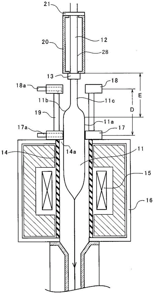
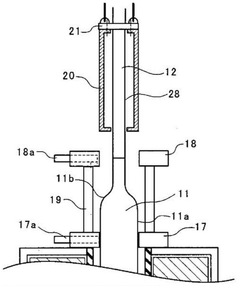
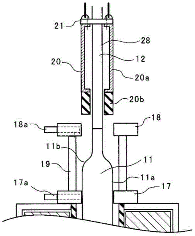
[0030] Next, specific examples of the optical fiber drawing method and the optical fiber drawing apparatus according to the embodiment of the present invention will be described with reference to the drawings.

[0031] In addition, although a resistance furnace in which a core tube is heated by a heater is described below as an example, the present invention can also be applied to an induction furnace in which a core tube is heated by induction by applying a high-frequency power supply to a coil.

[0032] exist figure 1 ~Among Fig. 4, 11 represents glass base material, 11a represents straight body portion, 11b represents taper portion, 11c represents diameter reducing portion, 12 represents assembly rod, 13 represents connecting member, 14 represents furnace tube, 15 represents heater, 16 17 denotes the first sealing part, 17a denotes the gas supply port, 18 denotes the second sealing part, 18a denotes the gas supply port, 19 denotes the upper chamber, 20 denotes the sleeve me...


PUM


Abstract

The purpose of the present invention is to reduce the spatial volume inside a drawing furnace so as to mitigate variations in pressure inside the furnace, and also stabilize sealing on the insertion opening side for glass base material. At the start of drawing, sealing is carried out at the outer peripheral surface of glass base material (11) by a first sealing part (17) of a sealing mechanism. After the proximity of a tapered part of the glass base material (11) starts passing through the first sealing part (17), a switch is made to a second sealing part (18) disposed above the first sealing part (17), and sealing is carried out by the second sealing member (18) at the outer peripheral surface of a sleeve member (20) affixed around the outer periphery of a dummy rod (12).

Description

technical field [0001] The invention relates to an optical fiber drawing method and a drawing device for heating and melting a glass base material for an optical fiber to draw an optical fiber. Background technique [0002] The drawing of an optical fiber in a drawing furnace is performed by heating and melting a glass base material for an optical fiber (hereinafter referred to as a glass base material) with a heater or the like. Since the temperature in the drawing furnace is greater than or equal to 2000°C, the temperature is very high. Therefore, graphite is usually used for the core tube surrounding the glass base material. This graphite is oxidized and consumed in a high-temperature oxygen-containing atmosphere. In order to prevent this, a rare gas such as argon or helium or nitrogen (hereinafter referred to as inert gas or the like) is fed into the drawing furnace. [0003] In addition, the upper end of the glass base material is usually tapered in diameter, connecte...

Claims


Application Information

Patent Timeline
Patent Type & Authority Applications(China)
IPC IPC(8): C03B37/027
CPCC03B37/02736C03B37/029C03B2205/80C03B2205/92
Inventor 冈崎岩山崎卓小西达也常石克之
Owner SUMITOMO ELECTRIC IND LTD
Learn More