Valve arrangement

A technology of valve device and valve housing, which is applied in the direction of fuel injection device, special fuel injection device, charging system, etc., can solve the problem of pump waste and achieve the effect of compact design and precise orientation

Active Publication Date: 2015-11-18
VTESCO TECH GMBH
View PDF3 Cites 1 Cited by
  • Summary
  • Abstract
  • Description
  • Claims
  • Application Information

AI Technical Summary

Problems solved by technology

However, the valve arrangement can only be tested directly in the pump for such a production

Method used


Image

  • Valve arrangement
  • Valve arrangement
  • Valve arrangement

Examples


Embodiment Construction

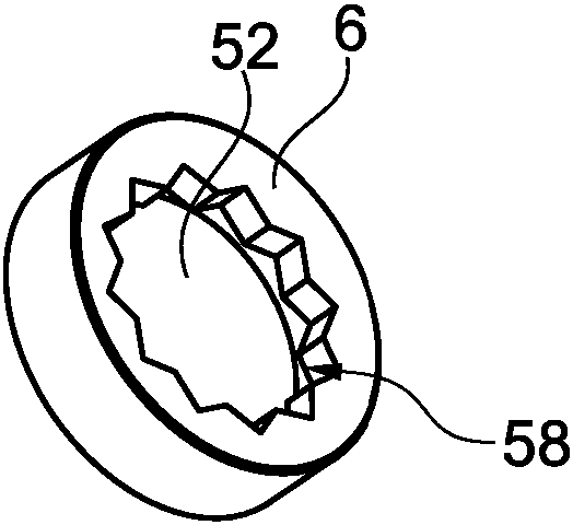
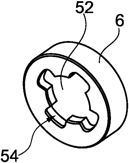
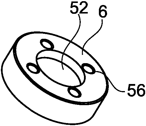
[0026] figure 1 A valve arrangement 2 is shown with a valve housing 4 , a clamping disk 6 and an actuator 8 in an actuator housing 10 . The core component of the valve arrangement 2 is the valve lifter 12 , which is pressed via a spring 14 against a stop 16 , wherein the actuator 8 is able to carry out an axial movement of the valve lifter 12 against the force of the spring. Depending on the electrical control flow, the opening area between the valve tappet 12 and the valve seat 60 is controlled by the actuator 8 . In this way the magnitude of the volume flow from fluid inlet 18 to outlet 20 is controlled.

[0027] In order to be able to inspect and / or replace individual components of the valve device 2 individually, the valve device 2 according to the invention has a functional mechanical separation which results in the structure shown. The valve housing 4 is configured in such a way that it can be inserted into the recess 22 of the pump housing 24 . This means that the va...


PUM


Abstract

A valve arrangement (2) for a high pressure pump is proposed, which valve arrangement (2) has a pump housing (24) with a depression (22), a valve housing (4) which is configured so as to correspond with the depression (22) in the pump housing (24), with the result that it can be inserted into the depression (22), and a clamping disc (6). The valve housing (4) has at least one radial projection (36) with a first axial boundary surface (5) and a second axial boundary surface (44) which is arranged so as to lie opposite said first axial boundary surface (5), wherein the clamping disc (6) extends radially over the radial projection (36) of the valve housing (4) and has a third axial boundary surface (46) which is configured so as to correspond with the second axial boundary surface (44) of the valve housing (4). On the circumferential side, the clamping disc (6) has a thread (40) which can be screwed into a thread (42) on the inner side of the depression (22) in such a way that the valve housing (4) is braced onto the first boundary surface (5).

Description

technical field [0001] The invention relates to a valve arrangement, in particular for a high-pressure pump for a common rail system. Background technique [0002] An injection system known as a common rail system for injecting fuel into a combustion chamber of an internal combustion engine, in particular a diesel engine, has a pressurized fuel accumulator, a common rail. High pressure pumps are required to continuously fuel these combustion chambers. [0003] In addition to a piston driven via an eccentric, high-pressure pumps also have valve arrangements with active or passive valves. As a rule, the valve arrangement is integrated directly into the pump with a high degree of integration in a sandwich design, which is produced, for example, by means of extrusion and welding operations and the accompanying setting process. For such production, however, the valve arrangement can only be tested directly in the pump, so that in the event of a functional failure of the valve t...

Claims


Application Information

Patent Timeline
IPC IPC(8): F02M59/36F02M59/46F02M59/48F02M59/44F04B1/04F02M63/02
CPCF02M59/366F02M59/44F02M59/466F02M59/48F02M63/0265F02M2200/8076F04B1/0452F04B53/10F02M59/36F02M59/46F02M59/485
Inventor A.米尔鲍尔M.布利克B.达格德伦J.伯恩哈特J.博曼
Owner VTESCO TECH GMBH
Why Eureka
Try Eureka