
Apparatus and methods for defining a plasma

A technology of plasma and equipment, applied in the field of plasma, can solve problems such as unsuitable substrates

Active Publication Date: 2015-11-18
CAMVAC
View PDF3 Cites 2 Cited by
  • Summary
  • Abstract
  • Description
  • Claims
  • Application Information

AI Technical Summary

Problems solved by technology

However, this coating system may not be suitable for applications where the substrate moves at higher linear speeds

Method used


Image

  • Apparatus and methods for defining a plasma
  • Apparatus and methods for defining a plasma
  • Apparatus and methods for defining a plasma

Examples


Embodiment Construction

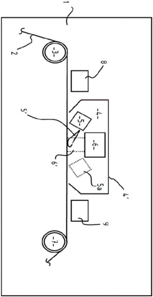
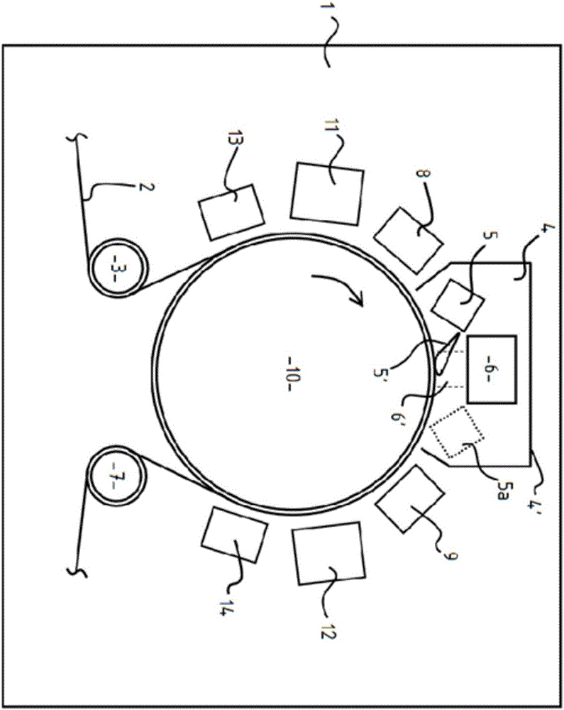
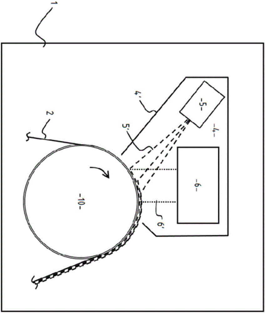
[0114] figure 1 The shown apparatus is housed in a vacuum chamber 1, and a coated substrate 2 to be treated is fed to a guide between a coated substrate unwinding (not shown) and a coated substrate rewinding chamber (not shown). On free guide rollers 3, 7, the coated substrate 2 is fed through a coating chamber 4, which is formed by an outer packaging 4' in which is placed a device for producing radiation curing. A radiation curing material directional beam generator 5 for a material directional beam 5', and a low-pressure gas plasma source 6 for generating a directional ion flow 6'. The directed ion flow may include cations as well as other positively charged or uncharged particles and species, however, only these positively charged ions are the primary initiators of the curing or treating process. Typical plasma ionization fractions can be in the range of 10 -5 to 10 -1 between. As the coated substrate passes beneath the radiation-curable material directional beam genera...


PUM

PropertyMeasurementUnit
Thicknessaaaaaaaaaa

Abstract

Apparatus comprising: a support 3, 7 arranged to transport a moving substrate 2, a plasma generator 6 arranged to generate plasma 6 and an electrode arranged to bias ions within the plasma towards the moving substrate 2 to form an ion flux. The ion flux has an energy level between 3.6eV and 250eV. The ion flux is used to cure radiation curable material on the moving substrate 2. Apparatus for defining plasma having a plurality of spaced race track portions using magnetic arrays is also disclosed (Fig. 9).

Description

technical field [0001] The invention relates to the field of plasma technology, in particular to a method and equipment for generating plasma. Background technique [0002] Coating relevant layers of cured polymers, metals or metal mixtures on coated substrates by coating processes such as vacuum coating processes can be made into films with enhanced barrier properties to oxygen or other gases, odors, and water vapor. These films are used in oxygen- or moisture-sensitive food packaging, encapsulation of gas- or moisture-sensitive components, and a variety of other functional applications requiring barrier properties. [0003] It is known to apply a cured polymer layer to the surface of a coated substrate by a vacuum plating process. However, both the known vacuum condensation process and the polymer precursor solidification process have a number of drawbacks / risks related to impurities in the raw materials used, especially commercial grades of raw materials used for the sub...

Claims


Application Information

Patent Timeline
IPC IPC(8): H01J37/32B05D3/06
CPCH01J37/32752B05D1/62B05D2252/02H01J37/32422H01J2237/3382Y02P20/582C08F2/46C08F2/52C08F2/54H01J37/32009H05H1/00H01J37/32H01J37/32403H01J37/32532H01J37/3266H01J37/3277H01J37/32036H01J37/32669H01J37/32715
Inventor 大卫·安东尼约翰·托平
Owner CAMVAC
Learn More