Injection process and injection equipment of chemical heat generating system in thick oil storage layer

A self-generating heat technology for heavy oil reservoirs, applied in chemical instruments and methods, production fluids, boreholes/well components, etc., can solve problems such as high risk factor, difficult implementation of injection technology, complex operation, etc.

Active Publication Date: 2015-11-25
CHINA UNIV OF PETROLEUM (EAST CHINA)
View PDF8 Cites 5 Cited by
  • Summary
  • Abstract
  • Description
  • Claims
  • Application Information

AI Technical Summary

Problems solved by technology

Since the active metal heat generation system involves dangerous goods such as active metal particles and strong alkali, it needs to be injected strictly according to multiple slugs. However, the existing conventional injection equipment and injection process are difficult to implement, and the operation is complicated and the risk factor is high.

Method used


Image

  • Injection process and injection equipment of chemical heat generating system in thick oil storage layer
  • Injection process and injection equipment of chemical heat generating system in thick oil storage layer
  • Injection process and injection equipment of chemical heat generating system in thick oil storage layer

Examples


Embodiment 1

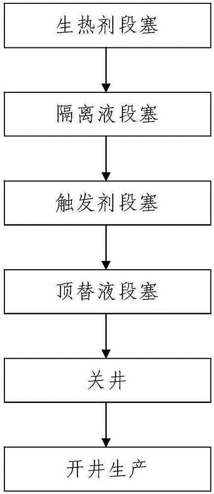
[0081] Such as figure 1 , figure 2 and image 3 The injection process of a chemical self-generating heat system in a heavy oil reservoir is shown, and the chemical self-generating heat system is injected into the heavy oil reservoir where the target well 8 is located by adopting a cold recovery method or a steam injection thermal recovery method; the chemical self-generating heat system It includes a heat generating agent and a triggering agent and it is an alkaline self-heating system or an acidic self-heating system, and the heat generating agent includes active wave metal particles with a particle size not greater than 400 mesh and a coating layer for wrapping active wave metal particles; The living wave metal particles of the alkaline self-generating heat system are aluminum powders, the coating layer used to wrap the aluminum powder is a paraffin coating layer or an aluminum stearate coating layer, and the trigger agent of the alkaline self-generating system is NaOH po...

Embodiment 2

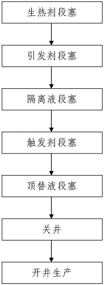
[0173] In this example, if figure 2 As shown, the difference from Example 1 is that the temperature T of the heavy oil reservoir where the target well 8 is located is less than or equal to 60°, and the chemical self-heating system is injected into the heavy oil reservoir where the target well 8 is located by adopting a cold recovery method, The process is as follows:

[0174] Step 301, heat generating agent slug: according to the method described in step 101, complete the heat generating agent slug process;

[0175] Step 302, initiator slug: inject the pre-prepared initiator solution into the heavy oil reservoir where the target well 8 is located; the initiator solution is a solution formed by uniformly mixing the initiator and water, and the initiator solution The mass concentration of the initiator in the medium is 35kg / m 3 ~45kg / m 3 ;

[0176] The injection volume of described initiator solution is 0.5m 3 ~1.8m 3 ;

[0177] Step 303, according to the method describe...

Embodiment 3

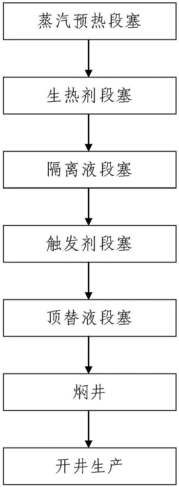
[0189] In this example, if image 3 As shown, the difference from Example 1 is that: the temperature T of the heavy oil reservoir where the target well 8 is located is > 120°, according to the method described in step 201 to step 204, the steam injection thermal recovery method is used to inject steam into the target well. The chemical self-heating system is injected into the heavy oil reservoir where 8 is located, and the process is as follows:

[0190] Step 201, steam preheating slug: Inject 280 to 320 tons of steam into the heavy oil reservoir where the target well 8 is located to preheat the heavy oil reservoir where the target well 8 is located;

[0191] Step 202, according to the method described in step 101 to step 104, complete the heat generating agent slug, spacer fluid slug, trigger agent slug and displacement fluid slug process from first to last;

[0192] Step 203, soaking the well: soaking the target well 8 for 3d to 7d;

[0193] Step 204, open the well for pro...


PUM

PropertyMeasurementUnit
particle sizeaaaaaaaaaa
viscosityaaaaaaaaaa

Abstract

The invention discloses an injection process of a chemical heat generating system in a thick oil storage layer; a cold production mode is used for injecting as follows: heat generating agent slug injection, separation liquid slug injection, trigger agent slug injection, replacement liquid slug injection, well closing and well opening production; a steam injection heat production mode is used for injecting as follows: steam preheating slug injection, heat generating agent slug injection, separation liquid slug injection, trigger agent slug injection, replacement liquid slug injection, well braising and well opening production; the process is simple in steps, reasonable in design, convenient to operate, safe and reliable in injection process and excellent in use effect, and can simply finish the injection process of the chemical heat generating system in the thick oil storage layer; moreover, the invention further discloses injection equipment of the chemical heat generating system in the thick oil storage layer; the equipment comprises four liquid mixing devices and one liquid injection pipe connected with a shaft of a target well; a plunger pump, a pressure detecting unit and a fifth one-way valve are mounted on the liquid injection pipe; and the equipment is simple in structure, reasonable in design, convenient for pipeline connection, simple in use and operation and excellent in use effect.

Description

technical field [0001] The invention belongs to the technical field of heavy oil exploitation, and in particular relates to a chemical self-generating heat system injection process and injection equipment in heavy oil reservoirs. Background technique [0002] Heavy oil resources are abundant, and its development is of great significance. A prominent feature of heavy oil reservoirs is that under formation conditions, heavy oil has high viscosity, high relative density, and poor flow capacity, so it is difficult to develop economically and effectively with conventional technologies. But the viscosity of heavy oil is very sensitive to temperature, that is, the viscosity of heavy oil decreases greatly when the temperature rises, and the higher the viscosity, the greater the drop. At this time, the flow of heavy oil tends to be Newtonian fluid, which is the most important factor for heavy oil. Thermophysical properties are also the basic basis for thermal oil recovery. Super hea...

Claims


Application Information

Patent Timeline
Patent Type & Authority Applications(China)
IPC IPC(8): E21B43/24C09K8/592
Inventor 吴飞鹏刘静蒲春生赵青黄小梅
Owner CHINA UNIV OF PETROLEUM (EAST CHINA)
Why Eureka
Try Eureka