Microgravity molecule heat-transferring heat conductor and application

A technology of microgravity and thermal conductors, applied in indirect heat exchangers, lighting and heating equipment, cooling/ventilation/heating transformation, etc., can solve problems such as inability to solve power dissipation above 100w, small application range, and inability to produce in large quantities. Achieve the effect of solving the problems of high-power heat dissipation and high heat flux heat conduction, unlimited scope of application, and cost-effective mass production

Inactive Publication Date: 2015-11-25
胡祥卿
View PDF5 Cites 4 Cited by
  • Summary
  • Abstract
  • Description
  • Claims
  • Application Information

AI Technical Summary

Problems solved by technology

[0002] The current heat sinks are common: 1. The heat sink directly processed by general metal materials (such as copper or aluminum) has the disadvantages of a waste of material, large volume, and heavy weight, which cannot solve the heat dissipation problem of power above 100w.
2. The disadvantage of heat sinks made of superconducting materials (such as superconducting plastics, liquid metals) is that the cost is too high, and the performance is only slightly improved on the basis of heat sinks directly processed from general metal materials, but the cost performance 3. The heat sink made of gravity heat pipe splicing has the disadvantages of high cost, large material waste, complicated process, unable to be mass-produced, and limited efficacy; 4. Heat sink made of phase change technology; currently The process of making radiators with variable technology is immature, the quality is unstable, and the cavity and shape cannot be designed arbitrarily according to needs. There is directionality when used, and the instantaneous temperature uniformity is poor. The amount of acetone used is large and there is no flammable degradation of the medium. Security risks
[0003] In addition, heat pipe technology and phase change technology are widely used in the preparation of heat conductors. The process of making high-power heat conductors with heat pipe technology is complicated, the cost is high, and the temperature uniformity of splicing is poor. The overall performance cannot meet the requirements of high-power heat dissipation, and It cannot overcome the dead angle of heat conduction, and cannot achieve instant temperature uniformity. The phase change technology has improved the heat pipe technology, but it cannot solve the problem of directional heat conduction. The heat sink formed cannot be used in the direction of Rehe, and the application range is small.
[0004] Furthermore, the heat transfer medium currently used in thermal conductors has a high boiling point, poor stability, and cannot be vaporized at low temperatures.

Method used


Image

  • Microgravity molecule heat-transferring heat conductor and application
  • Microgravity molecule heat-transferring heat conductor and application

Examples


Embodiment 1

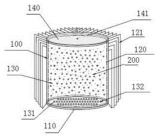
[0028] see figure 1 , the microgravity molecular heat transfer heat conductor provided in the figure includes a cylindrical heat sink 100, the bottom surface of the cylindrical heat sink 100 is the heat absorption surface 110, and the cylindrical surface is the heat dissipation surface 120, and the heat dissipation surface 120 is set There are several cooling fins 121, and the thickness of the root and end of the cooling fins 121 is 5:2-4. The radiator 100 and the radiator fins 121 are made of 6 series aluminum. ,

[0029] A cylindrical vacuum sealed chamber 130 is provided in the radiator 100 , and the interior of the cylindrical vacuum sealed chamber 130 must be conducted. The cylindrical vacuum sealed chamber 130 is filled with the microgravity molecular heat transfer medium 200 , and the volume of the microgravity molecular heat transfer medium 200 in liquid state at normal temperature is 2 / 5 of the volume of the vacuum sealed chamber 130 . The injection method of the m...

Embodiment 2

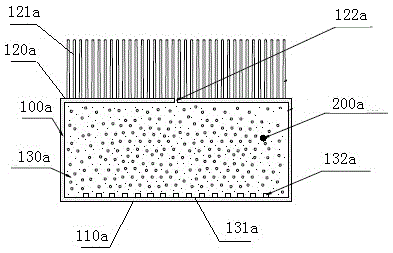
[0035] see figure 2 , the microgravity molecular heat transfer heat conductor provided in the figure includes a rectangular radiator 100a, the bottom surface of the rectangular radiator 100a is a heat-absorbing surface 110a, and the top surface is a heat-dissipating surface 120a. The heat sink 121a, the thickness of the root and end of the heat sink 121a is 5:2-4. The radiator 100a and the radiator fins 121a are made of 6-series aluminum. ,

[0036] A rectangular vacuum sealed cavity 130a is provided in the rectangular heat sink 100a, and the inside of the rectangular vacuum sealed cavity 130 must be conducted. The rectangular vacuum sealed chamber 130a is filled with the microgravity molecular heat transfer medium 200a, and the volume of the microgravity molecular heat transfer medium 200a in liquid state at room temperature is 2 / 5 of the volume of the rectangular vacuum sealed chamber 130a.

[0037] The injection method of the microgravity molecular heat conduction mediu...


PUM


Abstract

The invention discloses a microgravity molecule heat-transferring heat conductor. The microgravity molecule heat-transferring heat conductor comprises a radiator. The radiator is provided with a heat absorbing surface and at least one heat dissipating surface. A vacuum sealed cavity is arranged in the radiator. Microgravity molecule heat-transferring media with the volume being smaller than that of the vacuum sealed cavity are arranged in the vacuum sealed cavity. The microgravity molecule heat-transferring media are gasified rapidly when encountering a heat source under the microgravity condition, the whole sealed space is filled with the microgravity molecule heat-transferring media, part of heat energy is converted into molecule movement kinetic energy rapidly, and thus part of the heat energy is consumed; meanwhile, constant temperature is formed in the whole space rapidly, almost no heat resistance exists in the space, and a point heat source is changed into a body heat source instantly. The microgravity molecule heat-transferring heat conductor has the beneficial effects that the problems of high-power heat dissipation and high-heating-flux heat conduction are solved completely, manufacturing is convenient, the weight is low, cost is low, the conductor can be in any shape and be installed freely, and burning explosion hidden dangers are avoided. The microgravity molecule heat-transferring heat conductor is used for manufacturing high-power LED radiators or high-heating-flux integrated circuit board radiators.

Description

technical field [0001] The invention designs heat conduction technology, and in particular relates to a microgravity molecular heat transfer heat conductor and its application. Background technique [0002] The current radiators are common: 1. The radiators are directly processed by general metal materials (such as copper or aluminum). The disadvantages are that they are a waste of materials, large in size and heavy in weight, and cannot solve the heat dissipation problem of power above 100w. 2. The disadvantage of heat sinks made of superconducting materials (such as superconducting plastics, liquid metals) is that the cost is too high, and the performance is only slightly improved on the basis of heat sinks directly processed from general metal materials, but the cost performance 3. The heat sink made of gravity heat pipe splicing has the disadvantages of high cost, large material waste, complicated process, unable to be mass-produced, and limited efficacy; 4. Heat sink ...

Claims


Application Information

Patent Timeline
Patent Type & Authority Applications(China)
IPC IPC(8): F28D15/02H05K7/20F21V29/51F21Y101/02
Inventor 胡祥卿
Owner 胡祥卿
Why Eureka
Try Eureka