Closed-loop Hall current sensor

A current sensor, closed-loop Hall technology, applied in the field of sensors, can solve the problems of low precision, inconvenient installation, poor anti-interference ability, etc.

Inactive Publication Date: 2015-11-25
NINGBO HUAYU ELECTRONICS
View PDF3 Cites 7 Cited by
  • Summary
  • Abstract
  • Description
  • Claims
  • Application Information

AI Technical Summary

Problems solved by technology

However, the Hall current sensor in the prior art has the problems of low precision, poor anti-interference ability and inconvenient installation.

Method used


Image

  • Closed-loop Hall current sensor
  • Closed-loop Hall current sensor
  • Closed-loop Hall current sensor

Examples


Embodiment 1

[0067] The raw materials were weighed according to the composition and parts by weight of the ring mounting part in Example 1 in Table 1. Among them, the fibrous material is carbon fiber, the metal powder is iron powder with a particle size of 150nm, the antistatic agent is fatty acid polyol ester, the toughening agent is nano-calcium carbonate coated with POE-g-MAH, and the flame retardant is phosphorus-g-MAH. The nitrogen flame retardant, the formaldehyde absorber melamine, the formic acid absorber is sodium oxide, and the antioxidant is a commercially available antioxidant.

[0068] During preparation, the annular mounting part is made by injection molding, extrusion, extrusion or blow molding.

Embodiment 2

[0070] The raw materials were weighed according to the composition and parts by weight of the annular mounting part of Example 2 in Table 1. Among them, the fibrous material is carbon fiber, the metal powder is iron powder with a particle size of 150nm, the antistatic agent is fatty acid polyol ester, the toughening agent is nano-calcium carbonate coated with POE-g-MAH, and the flame retardant is phosphorus-g-MAH. The nitrogen flame retardant, the formaldehyde absorber melamine, the formic acid absorber is sodium oxide, and the antioxidant is a commercially available antioxidant.

[0071] During preparation, the annular mounting part is made by injection molding, extrusion, extrusion or blow molding.

Embodiment 3

[0073] The raw materials were weighed according to the composition and parts by weight of the ring mounting part of Example 3 in Table 1. Among them, the fibrous material is carbon fiber, the metal powder is iron powder with a particle size of 150nm, the antistatic agent is fatty acid polyol ester, the toughening agent is nano-calcium carbonate coated with POE-g-MAH, and the flame retardant is phosphorus-g-MAH. The nitrogen flame retardant, the formaldehyde absorber melamine, the formic acid absorber is sodium oxide, and the antioxidant is a commercially available antioxidant.

[0074] During preparation, the annular mounting part is made by injection molding, extrusion, extrusion or blow molding.


PUM

PropertyMeasurementUnit
particle diameteraaaaaaaaaa
impact strengthaaaaaaaaaa
particle diameteraaaaaaaaaa

Abstract

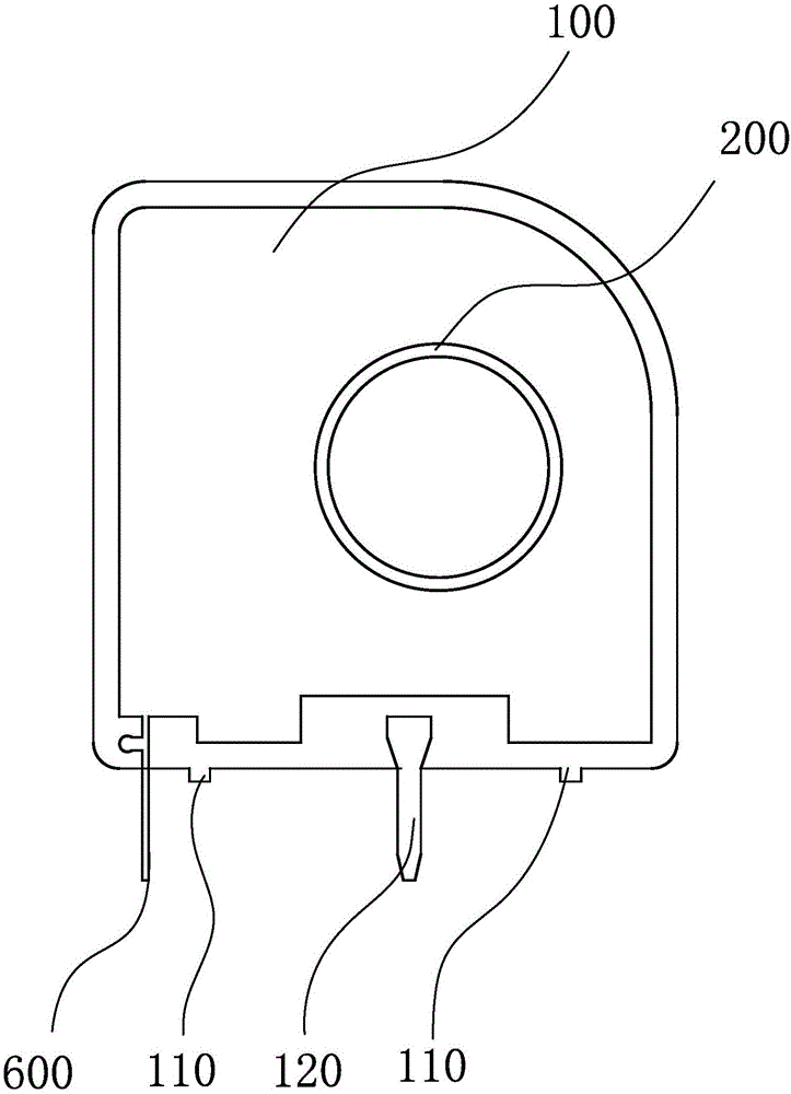
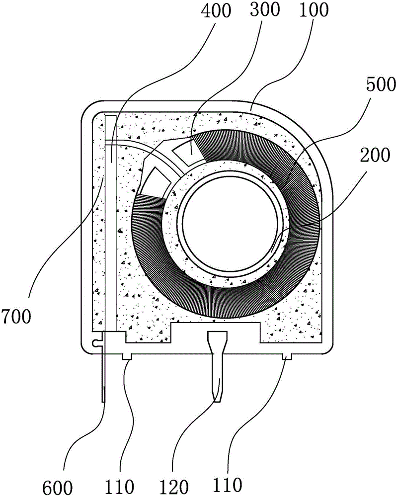
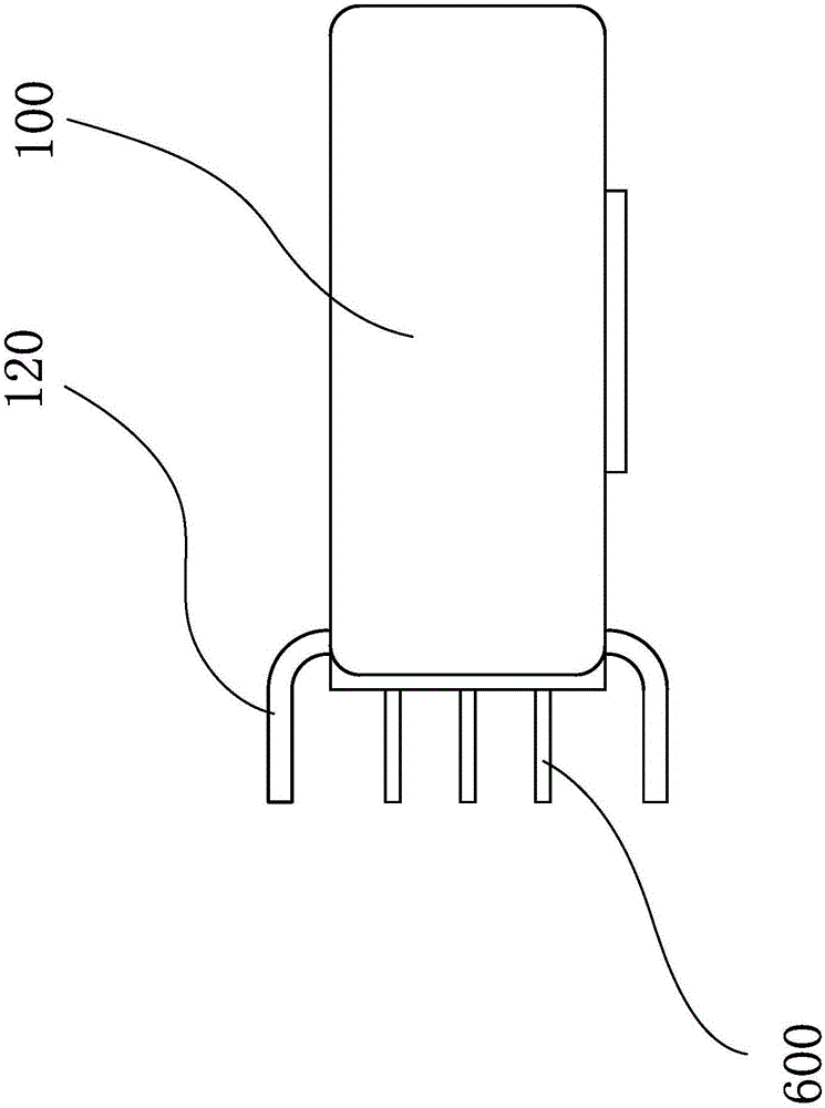
The invention provides a closed-loop Hall current sensor, belongs to the technical field of sensors, and solves problems that existing sensors are poor in anti-interference capacity. The closed-loop Hall current sensor comprises an insulating shell. The insulating shell is internally hollowed so that an accommodating cavity is formed. An annular magnetic core is transversely arranged in the accommodating cavity. The external surface of the annular magnetic core is provided with coils. The annular magnetic core is provided with a notch penetrating through the annular magnetic core. A Hall element is installed in the notch. An annular installing part penetrating through the insulating shell is arranged in the middle part of the annular magnetic core. The insulating shell is also internally provided with a circuit board. One end of the circuit board is respectively connected with the Hall element and the coils, and the other end of the circuit board extends so that a pin headers is formed. The pin head downwardly stretches out of the insulating shell The annular installing part is made of polyformaldehyde composite material. The closed-loop Hall current sensor has advantages of being high in sensitivity, high in anti-interference capability and convenient to install.

Description

technical field [0001] The invention belongs to the technical field of sensors and relates to a closed-loop Hall current sensor. Background technique [0002] The closed-loop Hall current sensor is based on the magnetic balance Hall principle, that is, when a current Ip passes through the main circuit, the magnetic field generated on the wire is gathered by the magnetic ring and induced to the Hall device, and the signal output generated by the Hall device is It can drive the power tube and turn it on, so as to obtain a compensation current Is, and this current generates a magnetic field through the multi-turn winding, which is exactly opposite to the magnetic field generated by the measured current, thus compensating the original magnetic field and making Hall The output of the device decreases gradually. When the magnetic field generated by Ip is equal to the magnetic field generated by Is, Is no longer increases. At this time, the Hall device plays the role of indicating ...

Claims


Application Information

Patent Timeline
Patent Type & Authority Applications(China)
IPC IPC(8): G01R19/00C08L59/00
Inventor 周年林王勇
Owner NINGBO HUAYU ELECTRONICS
Why Eureka
Try Eureka