Ridge waveguide planar array antenna employing mechanical center feeding

A center-fed, array antenna technology, used in antennas, antenna arrays, resonant antennas, etc., can solve the problems of inconvenient system design changes, antenna replacement, narrow bandwidth, and inability to meet high gain. Circularity, effect of expanding standing wave bandwidth

Inactive Publication Date: 2015-11-25
西安三维通信有限责任公司
View PDF10 Cites 22 Cited by
  • Summary
  • Abstract
  • Description
  • Claims
  • Application Information

AI Technical Summary

Problems solved by technology

[0003] The existing waveguide flat panel array antenna is equipped with a decoupling grid on the radiation layer to reduce the coupling interference between adjacent radiation slots, but the asymmetry of the horizontal and vertical structure and the mutual coupling between the radiation slots will affect the antenna direction. The out-of-roundness of the graph is not suitable for applications that require high out-of-roundness in the antenna pattern
In addition, the bandwidth of the existing waveguide flat panel array antenna is limited by the number of units. The more the number of units, the narrower the bandwidth, which cannot meet some applications with high gain and wide bandwidth requirements.
Moreover, the feeder port of the existing waveguide plate array antenna is mostly located on one side of the antenna array. When it is applied to other systems, it is necessary to design the support and connection structure for the position of the feeder port, which is not convenient for system design changes and replacement of other antennas.

Method used


Image

  • Ridge waveguide planar array antenna employing mechanical center feeding
  • Ridge waveguide planar array antenna employing mechanical center feeding
  • Ridge waveguide planar array antenna employing mechanical center feeding

Examples


Embodiment Construction

[0029] The present invention will be described in detail below in conjunction with the accompanying drawings and specific embodiments.

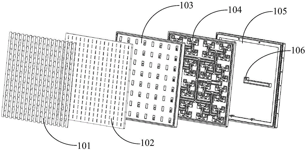
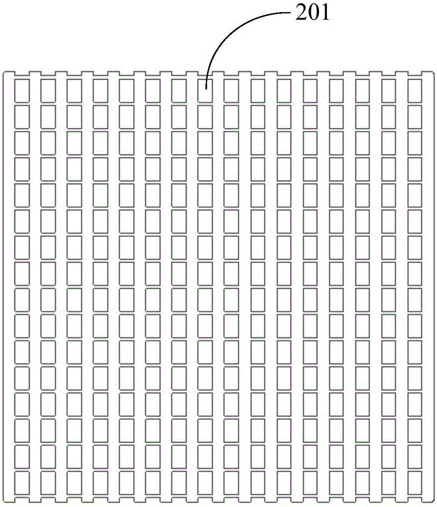
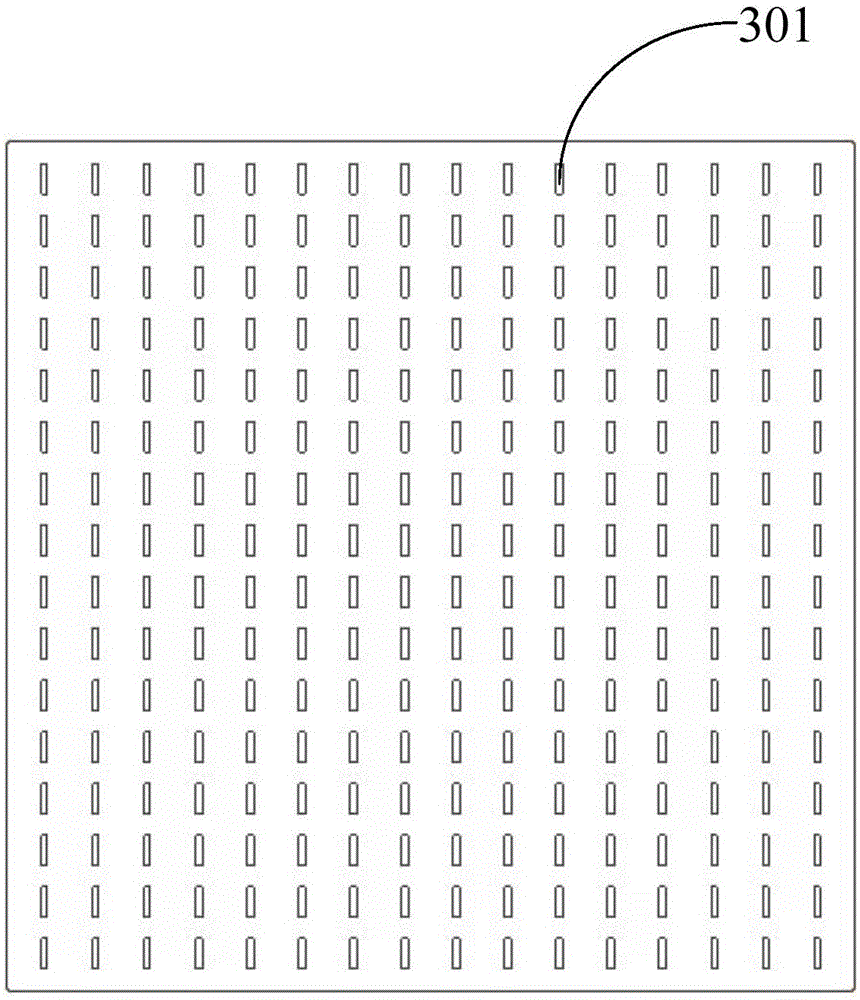
[0030] An embodiment of the present invention provides a mechanical center-fed ridge waveguide planar array antenna, such as Figure 1-7 As shown, the ridge waveguide planar array antenna includes a grid layer 101, a radiation layer 102, a coupling layer 103, a feed network layer 104, and a central feed layer 105 that are sequentially overlapped; the center of the central feed layer 105 is provided with a The waveguide port 106 for signal input and output; the feed network layer 104 is composed of a single ridge waveguide, and the center of the narrow side of each branch of the waveguide power divider 503 on the feed network layer 103 is provided with a ridge 501, and the ridge 501 Used to improve the standing wave bandwidth of the power splitter;

[0031] The substrate material of the ridge waveguide plate array antenna fed by the mechanica...


PUM


Abstract

The invention discloses a ridge waveguide planar array antenna employing mechanical center feeding. The ridge waveguide planar array antenna comprises a grid layer, a radiation layer, a coupling layer, a feed network layer and a center feed layer, which are sequentially stacked, wherein the mechanical center of the center feed layer is provided with a feeding opening which is vertical to an antenna array and is used for inputting and outputting a signal; the feed network layer is composed of a single ridge waveguide; and ridges are arranged at the centers of narrow sides of various branches of a ridge waveguide power divider on the feed network layer. Through introducing the grid layer and the center feed layer, adopting the design of a ridge waveguide power dividing network, and successfully combining with other structure layers, the targets of improving the out-of-roundness of an antenna radiation pattern, improving the antenna standing wave bandwidth and realizing mechanical center feeding of the antenna are achieved.

Description

technical field [0001] The invention belongs to the technical field of satellite communication and microwave communication panel antennas, and in particular relates to a mechanical center fed ridge waveguide panel array antenna. Background technique [0002] Compared with the traditional common reflector antenna, the waveguide plate array antenna has high mechanical strength and compact antenna structure, and will not cause corresponding unnecessary energy loss due to the irradiation of the feed source, and there is no feed source to block the radiation aperture. In terms of application to high-speed moving carriers, the waveguide flat plate array antenna has the characteristics of small size and low thickness. At the same time, the characteristics of being easy to share with the carrier make the antenna adaptable to air resistance or water resistance, and it is not easy to be damaged. Effectively reduce the The probability of antenna failure is reduced, and the service life...

Claims


Application Information

Patent Timeline
Patent Type & Authority Applications(China)
IPC IPC(8): H01Q9/04H01Q1/12H01Q21/00
Inventor 张小磊王孟
Owner 西安三维通信有限责任公司
Why Eureka
Try Eureka