Light source and method for producing the light source

A technology of light source and light emitting diode, applied in the field of light source, can solve the problems of poor volume and large size

Active Publication Date: 2015-11-25
CONTINENTAL AUTOMOTIVE TECH GMBH
View PDF5 Cites 4 Cited by
  • Summary
  • Abstract
  • Description
  • Claims
  • Application Information

AI Technical Summary

Problems solved by technology

Both measures reduce the manufacturing costs of standardized light sources, but especially the voltage converters used for boost conversion require relatively expensive or bulky cooling due to poor energy efficiency

Method used


Image

  • Light source and method for producing the light source
  • Light source and method for producing the light source
  • Light source and method for producing the light source

Examples


Embodiment Construction

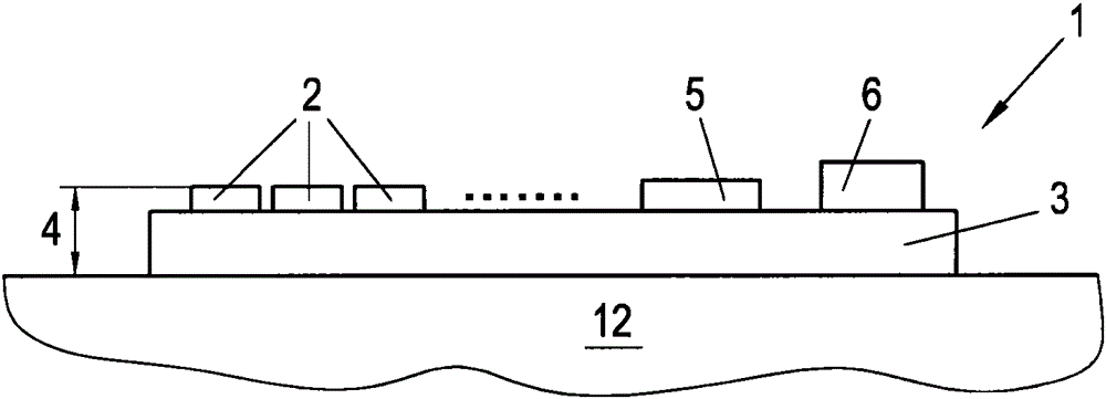
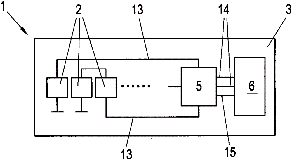
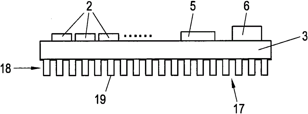
[0029] exist figure 1A side view of a light source 1 with a plurality of LEDs 2 is shown in . The LED 2 is an SMD component which is arranged on or connected to the circuit board 3 . The structural height 4 of the light source 1 in the area of ​​the LED 2 is approximately 4 mm in the present example. Furthermore, the printed circuit board 3 has a converter unit 5 , which is likewise assembled by means of SMD technology, and has a connector 6 for the electrical connection of the light source 1 to the vehicle electrical system or the headlight cable harness. The converter unit 5 is implemented as an integrated kit or system-in-package (SiP) and integrates at least one, preferably a plurality of buck converters 7 (see FIG. 5 ). The step-down converter 7 is provided for voltage conversion from the typical vehicle electrical system range of 6 to 18 V into the forward voltage of the LEDs, so that for example (in each case) two LEDs 2 connected in series can be supplied with a cons...


PUM


Abstract

The invention relates to a light source (1) and a method for producing said light source, for integration in a headlight having a circuit board (3), on which at least one light diode (LED) (2) and a converter unit (5) for supplying power to the LED (2) are arranged, wherein the converter unit (5) and the at least one LED (2) are designed as surface-mounted components (surface-mounted device, SMD) and the converter unit (5) has one or a plurality of buck converters.

Description

technical field [0001] The invention relates to a light source for integration in a headlamp having a circuit board on which at least one light emitting diode (LED) and a converter unit for supplying said LED are arranged; methods for making such light sources. Background technique [0002] Such light sources are increasingly being used, especially in the motor vehicle sector, in headlights for the main light function or signal light function and are typically combined with optical elements such as reflectors, projectors and light guides . [0003] A conventional LED main headlight used in practice has, for example, one or more LED modules and one or more separate electronic ballasts for supplying the LEDs with a constant current. The LED modules are connected to the ballast by means of plug-in connections and cable connections. Since pulse-width-modulated signals are used to control the LEDs, the lines required for this are radiated in areas that can cause disturbances i...

Claims


Application Information

Patent Timeline
Patent Type & Authority Applications(China)
IPC IPC(8): H05B33/08H05B44/00
CPCH05B33/0809H05B33/0845F21V23/005H05B45/10F21S41/151H05B45/375F21V29/70F21V29/89B60Q1/0088
Inventor M·奥斯特雷尔W·克尔纳
Owner CONTINENTAL AUTOMOTIVE TECH GMBH
Why Eureka
Try Eureka