Solar pyrolysis reactor

A reaction device, solar thermal technology, applied in solar thermal devices, solar thermal power generation, heating devices, etc., can solve the problems of unpredictability, high input cost of solar power generation, difficulty in grid connection, etc., and achieve high-efficiency conversion and high-value utilization. Effect

Inactive Publication Date: 2015-12-02
NORTHWEST A & F UNIV
View PDF6 Cites 18 Cited by
  • Summary
  • Abstract
  • Description
  • Claims
  • Application Information

AI Technical Summary

Problems solved by technology

[0005] In view of the problems and defects in the above-mentioned prior art, the purpose of the present invention is to provide solutions for the current situation that solar energy cannot be stored and transported on a large scale, the input cost of solar power generation is high, the power generation is intermittent, unpredictable, and difficult to connect to the grid. The strong heat-absorbing process of biomass pyrolysis is an opportunity for conversion. Using solar energy to provide heat to pyrolyze biomass to generate high-quality biogas and biochar, which solves the problems of poor solar stability and difficult storage, and greatly improves the efficiency of biogas. The final output provides a solar and biomass coupled energy utilization system

Method used


Image

  • Solar pyrolysis reactor

Examples


Embodiment Construction

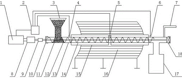
[0015] figure 1 A schematic structural view of the solar pyrolysis reaction device of the present invention is provided, which is composed of a pyrolysis system, a power system, a transmission system, a monitoring system and an auxiliary system. It is characterized in that the pyrolysis system consists of a trough solar reflector 16, The vacuum heat collector glass outer tube 15, the metal inner tube 13 of the pyrolysis reaction device and the heat-absorbing coating 14 on the outer wall of the metal inner tube, wherein the metal inner tube 13 of the pyrolysis reaction device is an integral part from the sealing head 10 to the bearing 18 The stainless steel pipe is covered with a heat-absorbing coating on the part with the glass outer tube of the vacuum heat collector, and the vacuum state is between the glass outer tube 15 of the vacuum heat collector and the metal inner tube 13 of the pyrolysis reaction device;

[0016] The power system is composed of a variable frequency mot...


PUM


Abstract

The invention discloses a solar pyrolysis reactor which is composed of a pyrolysis system, a power system, a transfer system, a monitoring system and an auxiliary system. Groove-type parabolic reflectors are utilized to focus direct light of sun, and a vacuum heat collection tube is used as an absorber; and the novel biomass pyrolysis reactor combines the solar direct metal-glass vacuum heat collection pipe and the biomass pyrolysis reactor. The solar energy is used as the heat source to directly pyrolyze the biomass, thereby generating biological combustible gas, biochar, wood vinegar and wood tar. The solar pyrolysis reactor is applicable to the fields of new rural community energy supply and modern ecological agriculture.

Description

technical field [0001] The invention relates to a solar pyrolysis reaction device. Background technique [0002] The energy crisis has become a worldwide problem and a bottleneck restricting the development of society and economy today. Conventional fossil energy reserves are limited and non-renewable, and the use of fossil energy has also caused serious environmental pollution and ecological damage. It is imperative to change the energy structure. Therefore, how to rationally develop and utilize renewable energy has become a major issue for human beings after entering the 21st century. new issues to face. [0003] Among the many renewable energy sources, solar energy and biomass energy are widely used. As a renewable new energy source, solar energy has the advantages of being clean, environmentally friendly, sustainable, and long-lasting. It has become one of the important choices for people to cope with energy shortages, climate change, and energy conservation and emissi...

Claims


Application Information

Patent Timeline
Patent Type & Authority Applications(China)
IPC IPC(8): C10B53/02H02S10/12H02K7/10F24J2/00
CPCY02E10/40Y02E10/50Y02E50/10Y02P20/133
Inventor 杨选民邱凌邱洪臣王雅君
Owner NORTHWEST A & F UNIV
Why Eureka
Try Eureka