Split assembled internal single cylinder diesel rear cover breather
A respirator, built-in technology, applied in the direction of machines/engines, mechanical equipment, engine components, etc., can solve the problems of poor diesel engine quality, complex product structure, loss of negative pressure effect, etc., to reduce the overall running resistance and reduce fuel consumption The effect of stabilizing the engine oil rate and reducing the engine oil consumption rate
- Summary
- Abstract
- Description
- Claims
- Application Information
AI Technical Summary
Problems solved by technology
Method used
Image
Examples
Embodiment 1
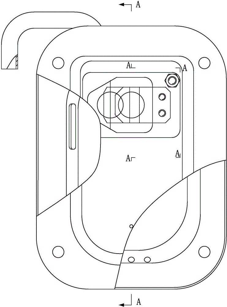
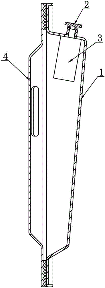
[0049] Embodiment 1: as Figure 3 to Figure 10 As shown, a split-assembled built-in single-cylinder diesel engine rear cover respirator is composed of a rear cover plate 1, an exhaust element 2, a respirator 3 and a full-covered oil baffle 4, and the respirator 3 is arranged on the rear cover plate 1, the respirator 3 and the exhaust element 2 are hermetically fixed on the rear cover 1 through a detachable structure, and the outlet end of the exhaust element 2 is set on the outside of the rear cover 1, and the respirator 3 The ventilation cavity 30 of the air exchange chamber is communicated with the outside world through the exhaust element 2; 31 is a shell with one side opening, the cavity of the shell seat 31 is the ventilation cavity 30, the breathing sheet stopper 34 is a spacer arranged in the ventilation cavity 30, and the spacer and the shell seat 31 are connected as In one body, a connection structure, a ventilation cavity 30, and a fixed installation structure for t...
Embodiment 2
[0050] Embodiment 2: The difference from Embodiment 1 is the detachable sealing structure between the respirator 3, the exhaust element 2 and the rear cover plate 1. In this example, as Figure 11 As shown, the detachable sealing structure between the respirator 3, the exhaust element 2 and the rear cover 1 is as follows: the rear cover 1 is provided with a ventilation installation hole 11, and on the side wall of the housing seat 31 An internal thread 37 is provided, and the internal thread 37 communicates with the ventilation cavity 30. The exhaust element 2 is a hollow stepped screw, which includes a connecting external thread 23, a vertical exhaust hole 24, a side exhaust hole 21 and a press fit Surface 25, side exhaust hole 21 communicates with vertical exhaust hole 24, the internal thread 37 on the shell seat 31 is aligned with the ventilation installation hole 11, and the connecting external thread 23 on the hollow step screw is screwed into the internal thread 37 , sea...
Embodiment 3
[0051] Embodiment 3: The difference from Embodiment 1 is the detachable sealing structure between the respirator 3, the exhaust element 2 and the rear cover plate 1. In this example, as Figure 12 As shown, the rear cover 1 is provided with a vent hole 12 and two installation holes 13, and the two installation holes 13 are arranged symmetrically outside the vent hole 12, and an air outlet 38 is provided on the side wall of the housing seat 31. And the screw hole 39, the air outlet hole 38 is in communication with the ventilation cavity 30, the setting positions of the air outlet hole 38 and the screw hole 39 correspond to the air hole 12 and the installation hole 13 on the back cover 1, and the exhaust element 2 includes The vertical exhaust hole 24, the side exhaust hole 21 and the connecting flange 26 are provided with two screw holes 27 on the connecting flange 26. Correspondingly, the vertical exhaust hole 24 corresponds to the vent hole 12 on the rear cover 1, and the res...
PUM
 Abstract
Description
Claims
Application Information
 - R&D
- Intellectual Property
- Life Sciences
- Materials
- Tech Scout
- Unparalleled Data Quality
- Higher Quality Content
- 60% Fewer Hallucinations
Browse by: Latest US Patents, China's latest patents, Technical Efficacy Thesaurus, Application Domain, Technology Topic, Popular Technical Reports.
© 2025 PatSnap. All rights reserved.Legal|Privacy policy|Modern Slavery Act Transparency Statement|Sitemap|About US| Contact US: help@patsnap.com


