A shaft connecting rod transmission system and an opposed piston engine

A technology of connecting rod transmission and opposed pistons, which is applied in transmission devices, machines/engines, mechanical equipment, etc., can solve the problems of complex limit mechanism, mechanical wear and noise, impact of left and right baffles, etc., and achieve simplified transmission system and Gas distribution system, reduce mechanical wear and noise, and eliminate the effect of transition impact

Active Publication Date: 2018-01-23
郑安庆
View PDF8 Cites 1 Cited by
  • Summary
  • Abstract
  • Description
  • Claims
  • Application Information

AI Technical Summary

Problems solved by technology

Its shortcoming is that, because the clutch internal tooth assembly inevitably swings during the movement process, the connecting rod also swings accordingly, so the connection between the connecting rod and the main working piston cannot be fixed, but only hinged, so it cannot be connected A sealing ring is set on the rod, so that the space between the back of the piston and the cylinder cannot be air-tight and cannot be used. The additional auxiliary piston, although the direct shaft drive is realized, the meshing of the transmission gear and the transmission rack is due to The swing of the inner tooth assembly is not reliable, and there are two abrupt steps on the arc-shaped convex edge of the reversing mechanism, which will cause greater impact, mechanical wear and noise to the left and right baffles, and the reliability of the operation cannot be guaranteed
Obviously, the gear transmission mechanism has the following deficiencies. Two sets of gear sleeve components must cooperate with each other to complete the reversing operation of the internal teeth. The corresponding piston and gear sleeve components must also be two sets and cannot be operated independently; the mechanism More parts will increase the inertial mass, which will have a negative impact on its operating efficiency; the limit mechanism is too complicated, which will increase manufacturing costs and reduce reliability and stability

Method used


Image

  • A shaft connecting rod transmission system and an opposed piston engine
  • A shaft connecting rod transmission system and an opposed piston engine
  • A shaft connecting rod transmission system and an opposed piston engine

Examples


Embodiment 1

[0042] Figure 6 to Figure 9 Shown is a two-stroke, opposed-piston engine. Taking the axis of the main shaft 10 as the reference center, the pistons close to the axis are called "inner pistons", and the pistons farther from the axis than the "inner pistons" are called "outer pistons". Equally, the axle-type connecting rod that is fixedly connected with " inside piston " is referred to as " inside axle-type connecting rod ", and the axle-type connecting rod that is fixedly connected with " outside piston " is called " outer frame shape axle-type connecting rod ".

[0043] refer to Figure 6 , Figure 7 , the opposed-piston engine of the present invention includes at least one pair of rectilinear reciprocating units arranged on the planes on both sides of the axis of the main shaft 10, and its rectilinear reciprocating unit A includes an inner piston 51a and an outer piston 51b arranged in the cylinder 50. The shaft connecting rod 40 includes an inner shaft connecting rod 40a...

Embodiment 2

[0054] Figure 10 and Figure 11 What is shown is a four-stroke opposed-piston engine, including at least one pair of linear reciprocating units arranged on the planes on both sides of the axis of the main shaft 10 , and the linear reciprocating body A is a piston 51 arranged in a cylinder 50 . The shaft connecting rod 40 is an inner shaft connecting rod 40a whose outer end is fixedly connected to the piston 51, the push-pull frame 20 is the first push-pull frame 20a, and the inner end of the inner shaft type connecting rod 40a is connected to the first push-pull frame. One side of 20a is fixedly connected. An intake valve 57 and an exhaust valve 58 are arranged on the outer end cover 52b of the cylinder 50, and a timing system is arranged between the main shaft 10, the intake valve 57, and the exhaust valve 58, and the timing system operates in a four-stroke mode. Gas distribution.

[0055] Described timing system can adopt multiple conventional devices, as belt timing sys...

Embodiment 3

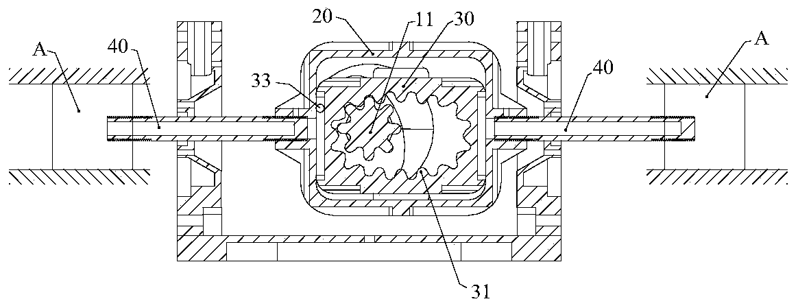
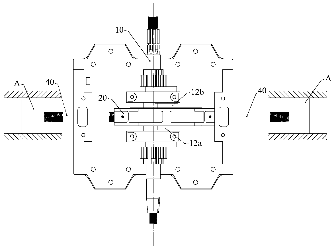
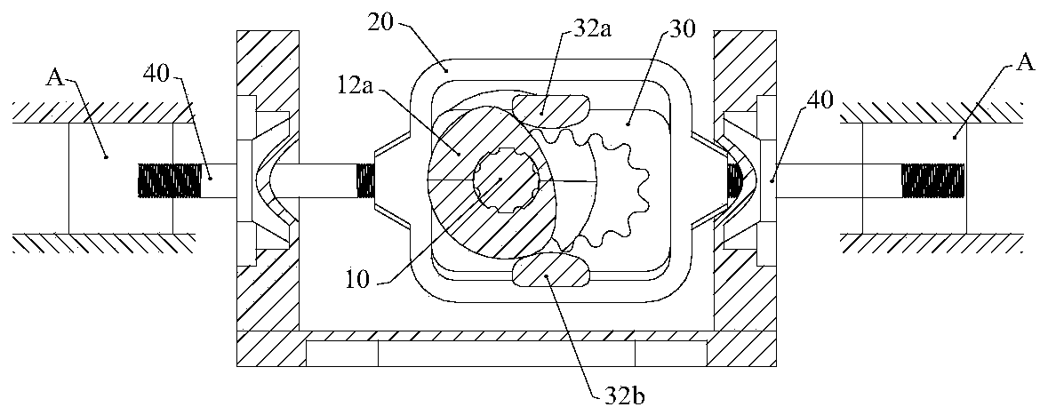
[0062] Figure 12 and Figure 13 Shown is a two-stroke opposed-piston engine, the opposed-piston engine includes at least a pair of linear reciprocating units arranged on the planes on both sides of the axis of the main shaft 10, and the linear reciprocating body A is arranged in the cylinder 50 Piston 51. The shaft connecting rod 40 is an inner shaft connecting rod 40 a whose outer end is fixedly connected to the piston 51 , and the push-pull frame 20 is the first push-pull frame 20 a. The inner end of the inner shaft connecting rod 40a is fixedly connected to one side of the first push-pull frame 20a, and an exhaust valve 58 is arranged on the outer end cover 52b of the cylinder 50, and a timing system is arranged between the main shaft 10 and the exhaust valve 58. , the timing system cooperates with the air inlet 55 controlled by the piston stroke to perform air distribution in a two-stroke working mode.

[0063] refer to Figure 13 , the timing system includes the oute...


PUM


Abstract

A shaft connecting rod transmission system and an opposed piston engine to convert reciprocating linear motion into rotary motion in the same direction, effectively improve the reliability of the transmission system, simplify the transmission system to make it more compact, and make the piston on the back of the internal combustion engine It is possible to effectively use the space between the cylinder and the cylinder. The shaft link transmission system includes a main shaft and at least one rectilinear reciprocating unit, and the rectilinear reciprocating unit includes at least one rectilinear reciprocating body. The linear reciprocating body is fixedly connected to one end of the corresponding shaft connecting rod, the other end of the shaft connecting rod is fixedly connected to one side of the corresponding push-pull frame, and the axes of the shaft connecting rod and the main shaft are perpendicular to each other. A sliding block is arranged in the push-pull frame, and the two lateral outer walls of the sliding block form a vertical sliding fit with the two lateral inner walls of the push-pull frame. The teeth are cyclically meshed with the gears correspondingly arranged on the main shaft. A reversing mechanism is arranged between the main shaft and the sliding block.

Description

technical field [0001] The invention relates to a shaft type connecting rod transmission system which converts linear reciprocating motion into rotary motion, and an opposed piston engine adopting the shaft type connecting rod transmission system. Background technique [0002] The most popular piston engine is the crankshaft connecting rod piston engine. The linear reciprocating motion of the piston is converted into the rotary motion of the crankshaft through the crankshaft connecting rod mechanism, but the crankshaft connecting rod mechanism reduces the efficiency of the piston engine and the fuel utilization efficiency. Only about 30%. [0003] In order to improve the efficiency of the piston engine, people are constantly improving the structure of the piston engine and its transmission system. [0004] For example, in the invention patent application specification with the publication number CN102003282, a kind of engine external pinion internal rack linkage mechanism i...

Claims


Application Information

Patent Timeline
Patent Type & Authority Patents(China)
IPC IPC(8): F02B75/32F02B75/24F16H37/12
Inventor 郑安庆
Owner 郑安庆
Why Eureka
Try Eureka