Special fault indicator for high-voltage power transmission network cable line

A fault indicator, cable line technology, applied in the fault location, instrument, measurement power and other directions, can solve the problem that the line maintenance personnel cannot effectively access the fault detection measurement signal, affect the detection accuracy of the pulse current method and other detection methods, and dismantle It is difficult to implement the head line, etc., to achieve the effect of flexible fault detection, light weight, convenient installation and debugging

Active Publication Date: 2015-12-02
STATE GRID CORP OF CHINA +1
View PDF9 Cites 16 Cited by
  • Summary
  • Abstract
  • Description
  • Claims
  • Application Information

AI Technical Summary

Problems solved by technology

But at present, while the safety of the cable interface is increasing, the terminals of the cable are all in the substation, and many of them are in the form of poles without outdoor terminals, which makes it impossible for line maintenance personnel to effectively access the measurement signals that need to be injected for fault detection. It is difficult to implement the method of dismantling the head wire, and the unplugging of the GIS cable terminal by the GIS air chamber is limited by the relevant personnel and equipment, and the reliability of the quality cannot be guaranteed.
[0006] In terms of the grounding method of the cable: since the fault current of the power cable with a voltage level of 110kV and 220kV is very large, the direct grounding method of the aluminum sheath and the grounding method through the arrester are adopted, so that the measurement signal is also affected by it, which seriously affects the pulse current method, etc. The detection accuracy of the detection method;
[0007] In terms of the structure of the cable itself: single-core cables are widely used in voltage levels of 110kV and above. Most of the cable lines are directly grounded, and some of them are high-resistance grounded. The traditional low-voltage bridge method and the traditional medium-voltage secondary pulse method are also difficult to implement, and the detection method has been greatly affected.

Method used


Image

  • Special fault indicator for high-voltage power transmission network cable line
  • Special fault indicator for high-voltage power transmission network cable line
  • Special fault indicator for high-voltage power transmission network cable line

Examples


Embodiment Construction

[0037] The present invention will be further described below in conjunction with specific drawings and embodiments.

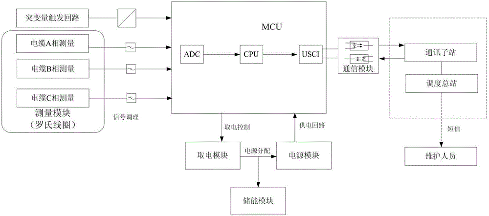
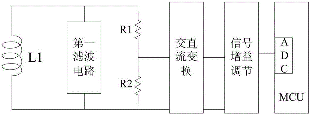
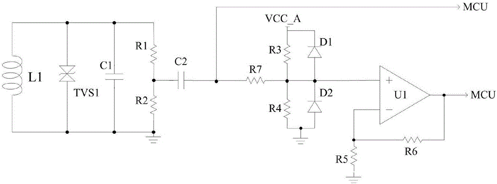
[0038] The present invention provides a special fault indicator for high-voltage transmission network cables (referred to as the fault indicator in this article), such as figure 1 As shown, including measurement module, power-taking module, power module, energy storage module, MCU and communication module;

[0039] The measurement module is connected to the ADC unit (i.e., the analog-to-digital conversion unit) in the MCU, and transmits the collected cable line current data to the central processing unit (i.e., the CPU) in the MCU through the ADC unit, and performs cable conversion through the central processing unit. Fault judgment; the communication module is used to upload the monitored cable line current data and the judged fault signal to the host system;

[0040] The upper system includes a communication sub-station and a dispatching central station. The...


PUM


Abstract

The invention provides a special fault indicator for a high-voltage power transmission network cable line. The special fault indicator comprises a measurement module, a power taking module, a power supply module, an energy storage module, an MCU (microprogrammed control unit) and a communication module, wherein the measurement module is connected with an ADC (analog-to-digital converter) unit in the MCU and is used for transmitting acquired current data of the cable line to a central processing unit in the MCU through the ADC unit and performing cable fault judgment through the central processing unit; the communication module is used for uploading the current data of the monitored cable line and fault signals obtained through judgment to an upper system; the power taking module is used for acquiring electric energy from the cable line through induction, is connected with the energy storage module and charges the energy storage module; the power taking module is connected with the power supply module and supplies power to the MCU; when the cable line has a fault, the energy storage module replaces the power taking module to supply stored power to the MCU. According to the special fault indicator for the high-voltage power transmission network cable line, effective electrical quantity detection can be performed on grounding faults and short-circuit faults of the high-voltage cable, and fast online fault positioning of a fault section is realized.

Description

technical field [0001] The invention relates to a special fault indicator for 110KV / 220kV power cables, which belongs to a fault section positioning device of a distribution network of a power system. It is mainly used in the short circuit and ground fault indication function encountered in the use of urban distribution network cables, especially for multi-branch cable lines and mixed overhead lines and cables. Background technique [0002] At present, with the development of the urban economy and the improvement of the quality of urban life, the transformation of power grids in many cities in my country is gradually accelerating. Among them, the 220kV and 110kV overhead lines will all adopt the cable-to-ground method. Beautifying the urban environment and improving urban functions will produce brand-new realistic effects. Cables are laid underground, which not only saves ground space, but also contributes to the beautiful appearance of the city; and the same underground cab...

Claims


Application Information

Patent Timeline
Patent Type & Authority Applications(China)
IPC IPC(8): G01R31/08G01R31/02
CPCY04S10/52
Inventor 何光华秦军缪家冬俞骏孙柯庄裕袁钦成郝海珍王亮朱秀香
Owner STATE GRID CORP OF CHINA
Why Eureka
Try Eureka