Method for manufacturing bearing ring member

A manufacturing method and component technology, which are applied to vehicle components, rotating components that resist centrifugal force, bearing components, etc., can solve the problems of increased processing cost, increased material cost, low machinability, etc., and achieve the effect of suppressing manufacturing cost and low cost.

Inactive Publication Date: 2015-12-02
NSK LTD
View PDF8 Cites 5 Cited by
  • Summary
  • Abstract
  • Description
  • Claims
  • Application Information

AI Technical Summary

Problems solved by technology

Therefore, as the material constituting the blank, although it is conceivable to use a single metal material with excellent fatigue strength and wear resistance when constituting the raceway surface, such as high-carbon chromium bearing steel (SUJ2-SUJ5), the price of this metal material is higher than that of Steel, etc. for machine

Method used


Image

  • Method for manufacturing bearing ring member
  • Method for manufacturing bearing ring member
  • Method for manufacturing bearing ring member

Examples


no. 1 approach

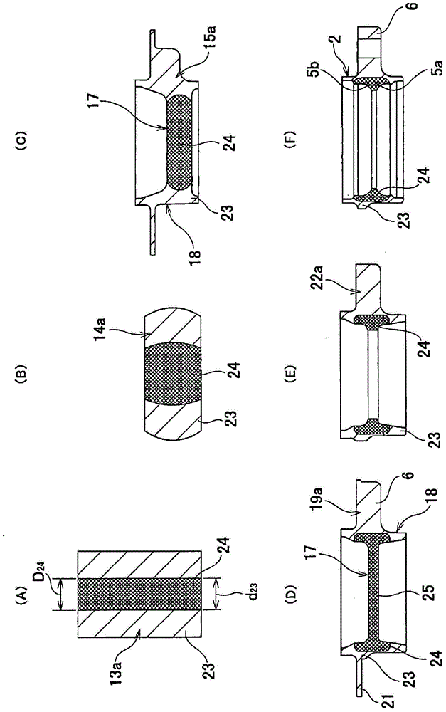
[0046] figure 1 (A)~ figure 1 (F) shows the first embodiment of the present invention. The object of the manufacturing method of the ferrule part of this example is the rolling bearing unit 1 for wheel support (refer to Figure 14 In addition to the outer ring 2 of ), the outer ring constituting various radial rolling bearings, the ball nut constituting the ball screw, and various ferrule parts with a raceway surface formed on the inner peripheral surface are also objects of this example .

[0047] In the manufacturing method of this example, first prepare figure 1 (A) The metal cylindrical blank 13a shown in FIG. In the case of this example, the blank 13a has the first metal part 23 and the figure 1 The second metal part 24 shown in diagonal grids. The first metal portion 23 is formed in a cylindrical shape by a metal member made of surface hardened steel such as machine structural steel or SCM420. When the second metal part 24 forms the outer ring raceways 5a, 5b of the ou...

no. 2 approach

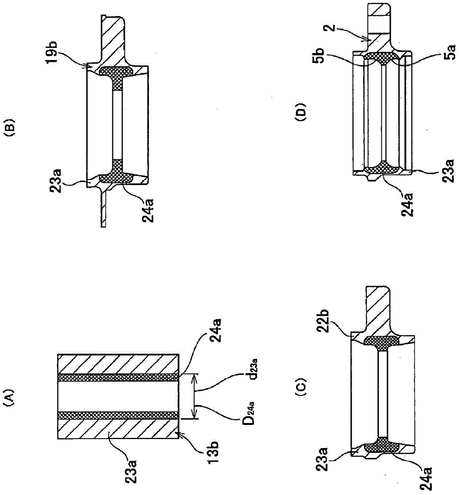
[0056] figure 2 (A) to figure 2 (D) shows the second embodiment of the present invention. In this example, as in the first embodiment, the rolling bearing unit 1 for wheel support (refer to Figure 14 ) Outer ring 2 is the object. In this example, prepare figure 2 The metal cylindrical blank 13b shown in (A). The blank 13b has a first metal part 23a and figure 2 The second metal part 24a is indicated by diagonal grids. The first metal portion 23a is formed in a cylindrical shape by a metal member made of surface hardened steel such as machine structural steel or SCM420. The second metal portion 24a is formed into a cylindrical shape by a metal member made of two types of high carbon chromium bearing steel (SUJ2) having higher fatigue strength or wear resistance than the first metal portion 23a when forming the outer ring raceways 5a, 5b. The outer diameter dimension D of the cylindrical metal member constituting the second metal portion 24a 24a And the inner diameter dimen...

no. 3 approach

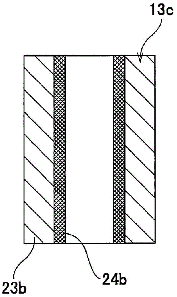
[0059] image 3 This shows the third embodiment of the present invention. In this example, as in the first embodiment, the rolling bearing unit 1 for wheel support (refer to Figure 14 ) Outer ring 2 is the object. In this example, prepare image 3 A cylindrical blank 13c made of metal is shown. The blank 13c is composed of a metal part such as mechanical structural steel and high-carbon chromium bearing steel. The radially outer cylindrical portion of the blank 13c, that is, the portion from the outer circumferential surface of the blank 13c to about 60% to 70% of the radial thickness, preferably from the outer circumferential surface of the blank 13c to the radial thickness Approximately 2 / 3 is the first metal part 23b. In addition, put the blank 13c in image 3 The cylindrical portion at the radially inner end shown in the diagonal lattice, that is, the portion from the inner peripheral surface of the blank 13b to about 30% to 40% of the radial thickness, preferably from th...


PUM


Abstract

Provided is a method for manufacturing a bearing ring member, whereby processing cost can be reduced and a high degree of freedom in design is obtained, by disposing a metal material of a raw material (13a), the metal material having excellent metal characteristics such as fatigue strength and abrasion resistance and excellent processing characteristics such as hardenability, in a portion that flows to a portion (raceway surface, etc.) where the characteristics of the metal material are required during use or forging of a bearing ring member. The present invention is configured from a first metal part (23) in which the raw material (13a) is formed in a cylindrical shape, and a second metal part (24) formed in a columnar shape by a metal material having more excellent metal characteristics or processing characteristics than the first metal part (23). For example, the second metal part (24) is disposed in a portion on an inside diameter side of the first metal part (23), which is a portion of the raw material (13a) that flows to an outer raceway (5a, 5b) of an outer ring (2) during forging.

Description

Technical field [0001] The present invention relates to a method of manufacturing a ferrule member that constitutes a rolling bearing or the like used in a rotation support part of various mechanical equipment, and has a raceway surface formed over at least one of the entire circumferential surface. Background technique [0002] Rolling bearings are assembled in the rotating support parts of various mechanical equipment including automobiles, machine tools, industrial machinery, and other general-purpose machinery. In addition, in various mechanical equipment, a ball screw device is sometimes incorporated as an axial feed device. As a member constituting such a rolling bearing and a ball screw device, there is a ring member in which a raceway surface is formed over the entire circumferential surface of at least one of the inner circumferential surface and the outer circumferential surface. Figure 14 As a rolling bearing used to rotatably support rotating parts for braking, such a...

Claims


Application Information

Patent Timeline
IPC IPC(8): B21K1/04F16C33/64
CPCB21J1/003B21K1/04B21K1/40F16C33/581F16C33/62F16C33/64B23P15/003F16C33/585F16C2220/46
Inventor 山本昌人小山宽小林一登
Owner NSK LTD
Why Eureka
Try Eureka