Permanent magnet, motor, and generator
A permanent magnet and atomic technology, applied in the field of electric motors and generators, permanent magnets, can solve the problem of square ratio reduction and other problems
- Summary
- Abstract
- Description
- Claims
- Application Information
AI Technical Summary
Problems solved by technology
Method used
Image


Examples
Embodiment approach 1
[0017] The permanent magnet of this embodiment will be described below.
[0018]
[0019] The permanent magnet of the present embodiment has the composition formula: R p Fe q m r Cu t co 100-p-q-r-t represented by the composition,
[0020] (wherein, R is at least one element selected from rare earth elements, M is at least one element selected from the group consisting of Zr, Ti, and Hf, and p satisfies 10.5≤p≤12.5 atoms %, q is a number satisfying 23≤q≤40 atomic %, r is a number satisfying 0.88≤r≤4.5 atomic %, t is a number satisfying 3.5≤t≤10.7 atomic %).
[0021] R in the above composition formula is an element that can make the magnet material have a large magnetic anisotropy. As the R element, for example, one or several elements selected from rare earth elements including yttrium (Y), such as samarium (Sm), cerium (Ce), neodymium (Nd), praseodymium (Pr ) etc., it is particularly preferable to use Sm. For example, when using a plurality of elements including Sm ...
Embodiment approach 2
[0073]The permanent magnet of Embodiment 1 can be used for various motors or generators. In addition, it can also be used as a fixed magnet or a variable magnet of a variable magnetic flux motor or a variable magnetic flux generator. By using the permanent magnet of Embodiment 1, various electric motors and generators are configured. In the case where the permanent magnet of Embodiment 1 is applied to a variable flux motor, Japanese Patent Laid-Open No. 2008-29148 or Japanese Patent Laid-Open No. 2008- The technology disclosed in the No. 43172 bulletin.
[0074] Next, a motor and a generator according to the present embodiment will be described with reference to the drawings. image 3 It is a figure which shows the permanent magnet motor in this embodiment. exist image 3 In the shown permanent magnet motor 1 , a rotor 3 is arranged inside a stator 2 . The permanent magnet 5 which is the permanent magnet of Embodiment 1 is arrange|positioned in the iron core 4 of the roto...
Embodiment 1、 Embodiment 2
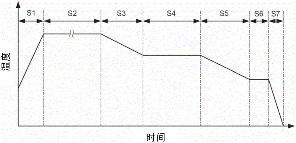
[0084] After weighing and mixing each raw material for a permanent magnet at a predetermined ratio, arc melting was performed in an Ar gas atmosphere to produce an alloy ingot. The alloy ingot was heat-treated by holding at 1180° C. for 12 hours, and then the alloy ingot was coarsely pulverized and pulverized by a jet mill to prepare alloy powder as a raw material powder of a magnet. The obtained alloy powder is press-formed in a magnetic field to produce a compression-formed body.
[0085] Next, arrange the compression molded body of the alloy powder in the cavity of the sintering furnace. After forming a vacuum state in the cavity, the temperature is raised to 1170° C. and kept at the reached temperature for 20 minutes. Then, Ar gas is introduced, and the temperature is raised to 1200° C., maintaining at the reached temperature for 6 hours, thereby performing sintering. Next, the sintered body was held at 1165° C. for 12 hours to perform solution treatment, and then cooled....
PUM
| Property | Measurement | Unit |
|---|---|---|
| The average diameter | aaaaa | aaaaa |
| Coercivity | aaaaa | aaaaa |
| The average particle size | aaaaa | aaaaa |
Abstract
Description
Claims
Application Information