Method for controlling pressure of silicon steel continuous annealing furnace separation section

A continuous annealing furnace, furnace pressure control technology, applied in the direction of heat treatment process control, furnace, heat treatment furnace, etc., can solve the problems affecting the furnace pressure gradient and stability of the furnace body, furnace pressure fluctuations in surrounding furnace sections, good isolation of difficult atmosphere, etc. , to achieve the effect of reducing the probability of interference, improving production efficiency and quality, and improving the effect of segmented isolation

Active Publication Date: 2015-12-09
WISDRI ENG & RES INC LTD
View PDF5 Cites 3 Cited by
  • Summary
  • Abstract
  • Description
  • Claims
  • Application Information

AI Technical Summary

Problems solved by technology

At present, the device used for the atmosphere isolation of the furnace section on the silicon steel line is composed of an isolation baffle, a discharge pipe, and a discharge regulating valve, but the control method is single, and the main method is to form a closed loop to adjust the furnace pressure in the isolation section and the discharge regulating valve.
However, this control method has the following problems: first, a single closed-loop adjustment, it is difficult to ensure a good furnace pressure difference under any circumstances, and it is difficult to achieve good isolation of the atmosphere; At the same time, the pressure of the furnace section will inevitably cause fluctuations in the furnace pressure of the surrounding furnace sections. When the annealing furnace needs to configure isolation section control for the atmosphere of multiple furnace sections, the independent control method of this isolation section will inevitably lead to a larger furnace section. Pressure fluctuations, which in turn affect the gradient and stability of the furnace pressure

Method used


Image

  • Method for controlling pressure of silicon steel continuous annealing furnace separation section
  • Method for controlling pressure of silicon steel continuous annealing furnace separation section
  • Method for controlling pressure of silicon steel continuous annealing furnace separation section

Examples


Embodiment Construction

[0031] In order to make the object, technical solution and advantages of the present invention clearer, the present invention will be further described in detail below in conjunction with the accompanying drawings and embodiments. It should be understood that this embodiment does not limit the scope of the present invention, and various changes and improvements made by those skilled in the art to the technical solution of the present invention shall fall within the scope of protection determined by the present invention.

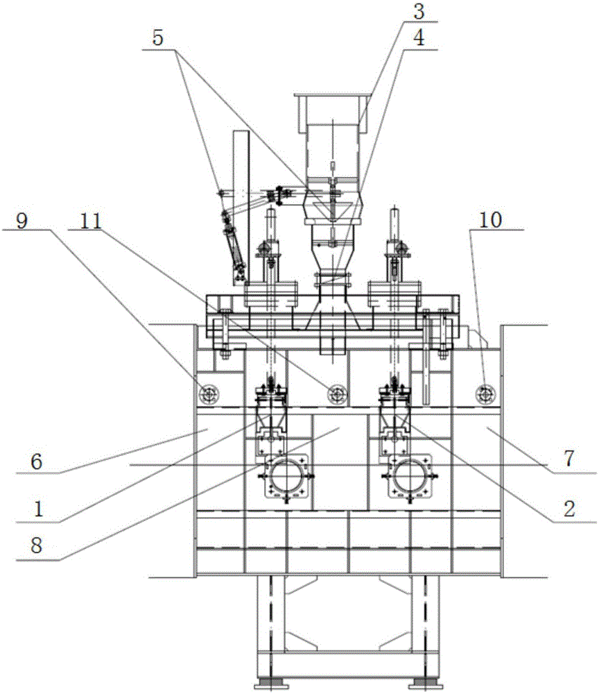
[0032] Such as figure 1 As shown, taking the 1# isolation section area as an example, the isolation section involved in the present invention is composed of 1# isolation baffle plate 1, 2# isolation baffle plate 2, release pipe 3, release regulating valve 4 and release isolation baffle plate 5, 1# Isolation baffle 1 and 2# Isolation baffle 2 isolate three atmospheres from 1# furnace area furnace gas 6, 2# furnace area furnace gas 7 and isolation section furn...


PUM


Abstract

The invention provides a method for controlling the pressure of a silicon steel continuous annealing furnace separation section. The method comprises the steps that the pressure P01 of a first furnace area, the pressure P02 of a second furnace area and the gas pressure P12 of a first furnace separation section are measured by a pressure transmitter and transmitted to an PLC control system; the PLC control system executes a PID parameter fuzzy-self-tuning program, PID parameters are obtained through calculation, then a PID controller outputs MV, and the MV is transmitted to a correlation computing controller; the PLC control system obtains a correction parameter J12 of a relief valve of the first separation section, finally, the output opening MV12=J12*MV of the relief valve of the first separation section is calculated through the correlation computing controller, and the MV12 calculation result is given to the relief valve of the first separation section to adjust the gas pressure of the separation section. On the condition of ensuring the air flow separation effect and the micro-positive pressure state of the separation section, the nitrogen protecting program starting frequency is reduced so as to reduce interference on pressure and gas in a furnace.

Description

technical field [0001] The invention belongs to the field of control methods for furnace section atmosphere barrier in silicon steel heat treatment process, and in particular relates to a furnace pressure control method in the isolation section of a silicon steel continuous annealing furnace. Background technique [0002] According to the heat treatment process of silicon steel, the dry atmosphere and wet atmosphere furnace section, the nitrogen-hydrogen mixed atmosphere furnace section with various ratios, the heating section and the cooling section all need to be isolated from the atmosphere. Pressure difference is achieved, so it is necessary to set up a sealing device for furnace pressure control. At present, the device used for the atmosphere isolation of the furnace section on the silicon steel line is composed of an isolation baffle, a release pipe and a release control valve, but the control method is single, mainly by forming a closed loop for adjustment of the furn...

Claims


Application Information

Patent Timeline
IPC IPC(8): C21D11/00C21D1/26C21D9/56
Inventor 张凯
Owner WISDRI ENG & RES INC LTD
Why Eureka
Try Eureka