Inductively coupled feed bending dipole RFID (radio frequency identification) tag antenna

An RFID tag and inductive coupling technology, applied in the field of bent dipole RFID tag antenna, can solve the problems that the size and function of the antenna cannot meet the miniaturization requirements of electronic equipment, increase the complexity of the antenna structure, etc. The effect of low profile and easy impedance matching

Active Publication Date: 2015-12-09
CENT SOUTH UNIV
View PDF6 Cites 10 Cited by
  • Summary
  • Abstract
  • Description
  • Claims
  • Application Information

AI Technical Summary

Problems solved by technology

[0004] However, in terms of antenna technology, the size and function of traditional antennas cannot meet the miniaturization requirements of electronic equipment
The size of the RFID antenna has become the "bottleneck" for the size reduction of RFID electronic equipment. Moreover, the RFID chip generally has the impedance characteristics of small resistance and large capacitance, which brings great problems to the matching of the antenna and the chip. Ordinary antennas often pass Additional circuitry to achieve impedance matching, which increases the complexity of the antenna structure

Method used


Image

  • Inductively coupled feed bending dipole RFID (radio frequency identification) tag antenna
  • Inductively coupled feed bending dipole RFID (radio frequency identification) tag antenna
  • Inductively coupled feed bending dipole RFID (radio frequency identification) tag antenna

Examples


Embodiment Construction

[0024] The present invention will be described in detail below in combination with specific embodiments.

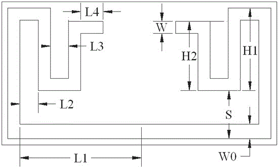
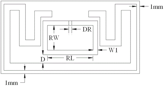
[0025] The present invention includes a substrate 1 , a radiator 2 and a feeding ring 3 . The radiator 2 and the feeding ring 3 are mounted on the front side of the substrate 1 . The radiator includes a U-shaped part. The two ends of the U-shaped part extend inwardly and at least one bent part is provided. The end of the bent part located in the innermost part extends horizontally and has a bent end. The feeding ring has a rectangular structure and is formed by the U The inside of the shape part, the inside of the innermost bend part and the end of the bend are surrounded. The bent end can significantly increase the coupling strength between the feed loop and the radiator and improve the radiation characteristics.

[0026] The schematic diagram of the antenna structure is as figure 1 As shown, the parameters of the antenna in this embodiment are described as follows. ...


PUM


Abstract

The invention discloses an inductively coupled feed bending dipole RFID (radio frequency identification) tag antenna, which comprises a substrate, a feed ring and a radiator, wherein the radiator adopts a non-uniform bending bilaterally symmetrical structure, multiple groups of adjustable parameters are provided, and parameter combination is adjusted so as to realize adjustment for the antenna performance. The feed ring is of a rectangular structure and is surrounded in the radiator, and adjustment can be carried out on the antenna performance by changing the size of the feed ring. The inductively coupled feed bending dipole RFID tag antenna has the characteristics of small size, omnidirectional radiation, simple structure, easiness in realizing impedance matching and the like, thereby being capable of achieving a purpose of miniaturizing an RFID antenna, and being capable of meeting specific requirements of an RFID application system for the antenna.

Description

technical field [0001] The invention belongs to the technical field of antennas, and relates to an ultra-high frequency RFID tag antenna size optimization design method, in particular to a bent dipole RFID tag antenna with inductive coupling feeding. Background technique [0002] Radio frequency identification (radio frequency identification, RFID) is a non-contact automatic identification technology that uses radio frequency signals. Because it has the advantages of fast transmission rate, large-scale reading and motion process reading, it has been applied in manufacturing and counterfeit identification. , logistics management and public safety and other fields. [0003] In recent years, with the rapid development of wireless communication technology and chip technology, RFID technology has developed rapidly, further expanding the application of RFID antennas. In addition, it can be further integrated with other wireless technologies. For this reason, RFID, together with t...

Claims


Application Information

Patent Timeline
Patent Type & Authority Applications(China)
IPC IPC(8): H01Q1/38H01Q1/50H01Q1/22
Inventor 董健胡国强白永恒施荣华
Owner CENT SOUTH UNIV
Why Eureka
Try Eureka