
Temperature-controlled metal casting method

A metal casting and metal technology, applied in the field of temperature-controlled metal casting, can solve the problems of non-dense internal structure, high energy consumption, and uneven grain size of castings, and achieve compact internal structure, uniform grain size, and production efficiency. high effect

Active Publication Date: 2015-12-16
JIANGSU HUAWEI COPPER IND
View PDF9 Cites 4 Cited by
  • Summary
  • Abstract
  • Description
  • Claims
  • Application Information

AI Technical Summary

Problems solved by technology

[0006] In order to overcome the problems of high energy consumption in casting, non-dense internal structure of castings, and uneven grain size in the prior art, the present invention provides a temperature-controlled metal casting method, using the preparation process provided by the present invention, The cast metal castings have high surface gloss, dense internal structure, uniform grain size, high plasticity and high quality

Method used

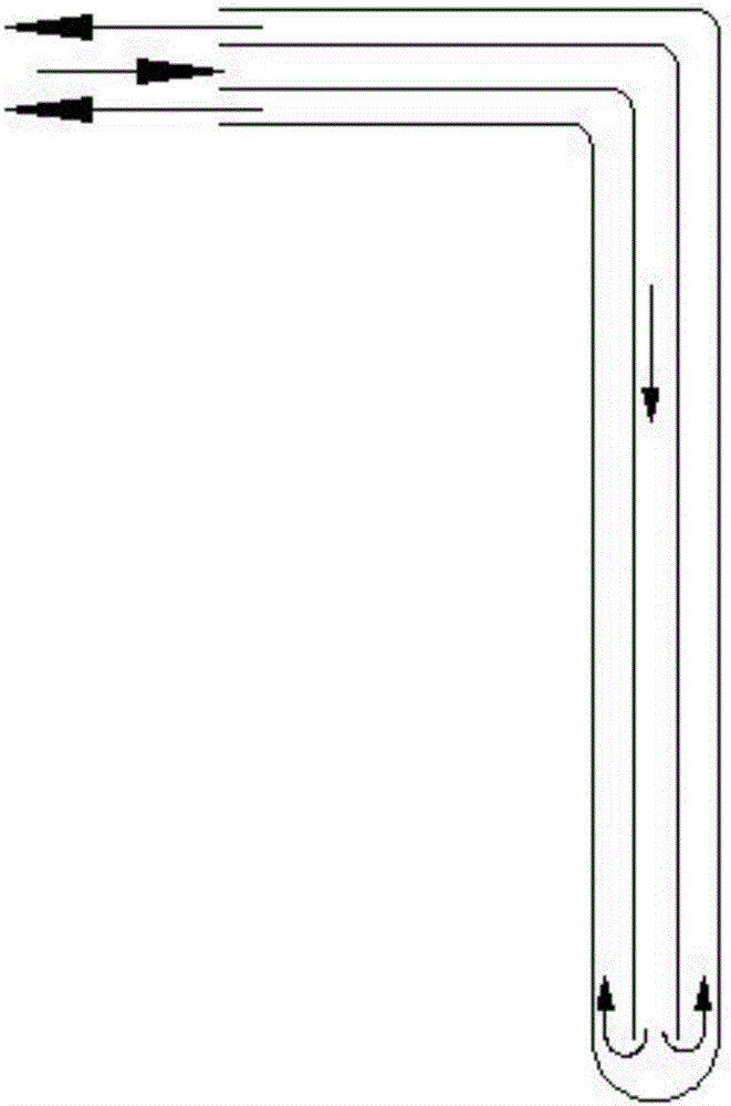
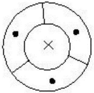

Image

  • Temperature-controlled metal casting method
  • Temperature-controlled metal casting method
  • Temperature-controlled metal casting method

Examples


Embodiment 1

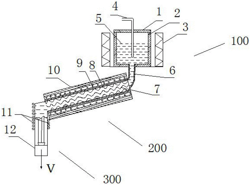
[0058] like figure 1 As shown, a temperature-controlled metal casting device includes a material holding device 100, a homogenizing device 200, and a stretching device 300; wherein, the material holding device 100 includes a crucible 1, a crucible top cover 2, an electromagnetic stirrer 3, and a flow guide Pipe 6; Homogenizing device 200 includes spiral pipeline 7, inner insulation layer 8, cooling pipe 9, outer insulation layer 10; Stretching device 200 includes heating device 11 and traction mechanism 12; Electromagnetic stirrer 3 wraps around the feeding device . In addition, the connection relationship between the material holding device 100, the homogenizing device 200, and the stretching device 300 is: the upper end of the homogenizing device 200 is connected to the draft tube 6 below the material holding device 100, and the stretching device 300 is connected to the lower end of the homogenizing device 200 .

[0059] The material holding device 100 of the above-mention...

Embodiment 2

[0064] Can refer to Figure 1-3 The apparatus diagram, a kind of temperature control type metal casting method, comprises the following steps:

[0065] Step 1: Stir the molten metal 5 in the crucible 2 to achieve uniform composition mixing and uniform temperature distribution; conduct heat from the center of the crucible 2 in time through the heat conducting rod 4 at the center of the crucible 2;

[0066] Step 2: Flow the molten metal 5 in the crucible 2 into the homogenization device 200 through the draft tube 6;

[0067] Step 3: through the action of the spiral pipe 7 of the homogenization device 200, the metal solution 5 is formed into a homogenized turbulent flow, and under the action of the cooling pipe 9, the temperature of the metal at the outlet of the homogenization device 200 is reduced to below the solidus line;

[0068] Step 4: Control the temperature of the pre-stretched metal through the heating device 11 on the upper part of the traction mechanism 12; under the...


PUM


Abstract

The invention provides a temperature-controlled metal casting method. The method includes the steps that firstly, molten metal in a crucible is stirred so as to be uniform in ingredient mixing and temperature distribution; secondly, the molten metal in the crucible flows into a homogenization device through a flow guide pipe; thirdly, the molten metal forms a homogenized turbulent flow under the effect of a spiral pipeline of the homogenization device, and the temperature of metal at an outlet of the homogenization device is lowered to below a solid phase line under the effect of a cooling pipeline; fourthly, the metal at the outlet of the homogenization device is continuously drawn into a metal casting blank under the effect of a drawing device. By means of the temperature-controlled metal casting method, a prepared metal casting is high in surface gloss, compact in internal structure, uniform in grain size, free of segregation and cracks and high in plasticity and quality; besides, energy is saved, the process is simplified, and production efficiency is high.

Description

technical field [0001] The invention relates to the technical field of metal casting, in particular to a temperature-controlled metal casting method. Background technique [0002] Metal casting is a process in which metal is smelted into a liquid that meets certain requirements and poured into a mold, cooled and solidified, and cleaned to obtain a casting with a predetermined shape, size and performance. It plays a pivotal role in the production of metals. With the continuous increase of metal materials and product varieties, the rapid expansion of application fields, the rapid development of high-tech and the improvement of people's living standards, the world is facing the current situation of environmental degradation, resource and energy shortages, and the energy saving of metal casting process The requirements for consumption reduction, short process, high efficiency, low cost and slab quality are getting higher and higher. [0003] At present, the molds used in metal...

Claims


Application Information

Patent Timeline
IPC IPC(8): B22D1/00B22D11/18
Inventor 肖康才洪钢肖康明
Owner JIANGSU HUAWEI COPPER IND
Learn More