Flammable gas recycling thermal treatment furnace

A technology for heat treatment furnace and gas import, which is used in coke ovens, special forms of dry distillation, and petroleum industry. Utilization, easy maintenance, high heat utilization effect

Active Publication Date: 2015-12-16
托普工业(江苏)有限公司
View PDF5 Cites 3 Cited by
  • Summary
  • Abstract
  • Description
  • Claims
  • Application Information

AI Technical Summary

Problems solved by technology

[0004] In the actual use process, according to the applicant's report, although the carbonization furnace can better realize the recycling of the combustible gas produced in the carbonization process, it has certain problems: the carbonization furnace is equipped with both the carbonization chamber and the combustion chamber In the furnace body, and the two are connected through the carbonization gas outlet pipe. Due to the high temperature inside the furnace body, the carbonization gas outlet pipe is easy to age when placed in the furnace body for a long time, and has a short lifespan and is not easy to overhaul, posing a safety hazard. In addition, from It can be seen from the accompanying drawings that there are several small holes evenly distributed on one end of the carbonization gas outlet pipe placed in the carbonization tank. Although these small holes are beneficial to the output of combustible gases everywhere in the carbonization chamber, the combustible gas generated during the carbonization process usually contains A large amount of dust, particulate matter and oil gas will easily block the small holes, affecting the normal operation of the carbonization gas outlet pipe, and the energy recovery rate is low

Method used


Image

  • Flammable gas recycling thermal treatment furnace
  • Flammable gas recycling thermal treatment furnace
  • Flammable gas recycling thermal treatment furnace

Examples


Embodiment

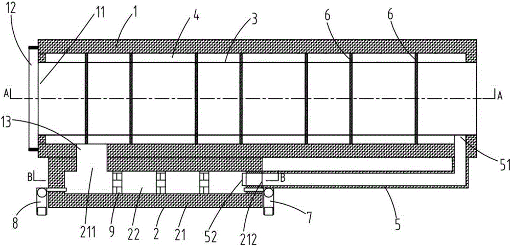
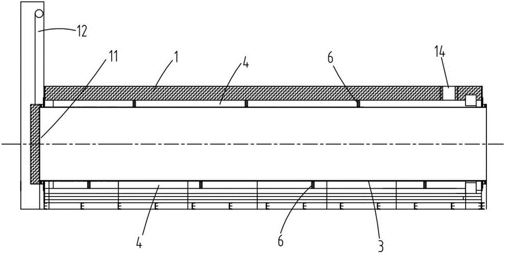
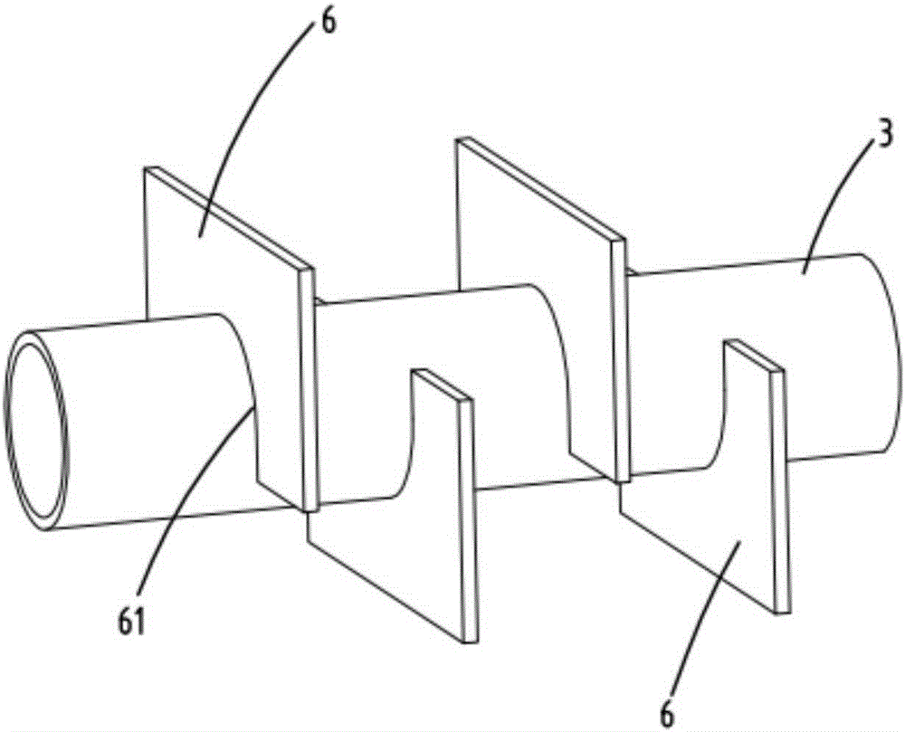
[0031] Such as figure 1 As shown, the present invention provides a combustible gas recycling heat treatment furnace, including a furnace body 1, a combustion chamber 2 equipped with a burner, and a waste gas discharge pipe 5, and a furnace chamber 3 for heat treatment of materials is provided in the furnace body 1, as shown in FIG. figure 2 As shown, the feed end 11 of the furnace body 1 is provided with a furnace door 12 that can be opened or closed, wherein the furnace body 1 is square, and the furnace furnace 3 is cylindrical. In the closed annular hot gas duct 4 , a high-temperature flue gas inlet 13 and a flue gas outlet 14 communicating with the hot gas duct 4 are provided on the furnace body 1 . The combustion chamber 2 includes a housing 21 with a combustion chamber 22 inside. The housing 21 can be designed as a cuboid, cube or other shapes as a whole. The housing 21 is provided with a gas injection port 211 and a gas inlet communicating with the combustion chamber 22...


PUM


Abstract

The invention relates to a flammable gas recycling thermal treatment furnace which comprises a furnace body, a combustion chamber provided with a combustor and an exhaust discharge pipe, wherein a furnace pipe is arranged in the furnace body, a furnace door is arranged at a feeding end, a closed annular hot air channel is formed between the inner wall of the furnace body and the outer wall of the furnace pipe, and a high-temperature glue gas inlet and a flue gas exhaust opening are formed on the furnace body; the combustion chamber comprises a housing which is internally provided with a combustion cavity, wherein an air jet hole and a gas inlet are formed on the housing, the combustion chamber is arranged out of the furnace body, the air jet hole is communicated with the high-temperature flue gas inlet on the furnace body, and the gas inlet of the exhaust gas discharge pipe is communicated with the inner side of the furnace pipe and the gas outlet of the exhaust gas discharge pipe extends into the combustion cavity through the gas inlet on the combustion chamber. According to the furnace provided by the invention, the combustion chamber and the furnace body are independently arranged, the exhaust gas discharge pipe introduces flammable gas generated in the furnace pipe into the combustion chamber to be combusted, and high-temperature flue gas generated by combustion is introduced into a hot air channel to supply energy for thermal treatment, so that energy sources are recycled, the energy consumption is reduced, and the furnace is energy-saving and environmental-friendly, easy to overhaul, simple in integral structure and low in cost.

Description

Technical field: [0001] The invention relates to the field of pyrolysis equipment, in particular to a combustible gas recycling heat treatment furnace. Background technique: [0002] Recently, due to the use of pyrolysis and carbonization to obtain clean or modified fuels, it can not only reduce the environmental pollution caused by direct combustion of solid fuels, but also make full use of the compounds of high economic value contained in solid fuels, which is energy-saving, environmentally friendly and rationally utilized. The broad meaning of resources has gradually been adopted by the industry. In recent years, on the basis of the traditional carbonization furnace, some improvements have been made to the carbonization furnace body, pyrolysis gas recovery and preheating utilization, and a carbonization furnace with a corresponding structure has been designed and developed to improve the carbonization efficiency and reduce the energy consumption of the system . [0003]...

Claims


Application Information

Patent Timeline
Patent Type & Authority Applications(China)
IPC IPC(8): C10B53/00
Inventor 沈润良
Owner 托普工业(江苏)有限公司
Why Eureka
Try Eureka