
Energy-saving chilled water storage structure

A water cold storage and energy-saving technology, which is applied in the field of energy storage, can solve the problems of low utilization rate of cooling capacity, slow cooling, poor quality of air-conditioning, etc., and achieve good cooling effect, fresh air, and energy-saving effects

Inactive Publication Date: 2015-12-16
许文辉
View PDF7 Cites 6 Cited by
  • Summary
  • Abstract
  • Description
  • Claims
  • Application Information

AI Technical Summary

Problems solved by technology

[0006] The object of the present invention is to solve the above-mentioned problems in the prior art, and provide an energy-saving water cold storage structure, which has high refrigeration efficiency, high utilization rate of cooling capacity, fresh cold air, and low electricity price, which solves the problem There are problems such as low utilization rate of cooling capacity of water storage structure, slow cooling, poor quality of air-conditioning, etc.

Method used


Image

  • Energy-saving chilled water storage structure
  • Energy-saving chilled water storage structure
  • Energy-saving chilled water storage structure

Examples


Embodiment Construction

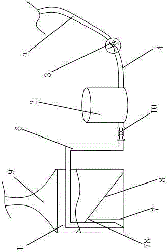
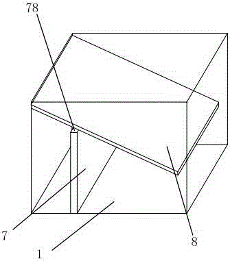
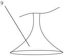
[0029] like Figure 1 to Figure 3 As shown, the water cold storage structure includes a square cylindrical cold storage tank 1, the outer wall of the cold storage tank 1 is wrapped with a layer of insulation layer, the cold storage tank 1 has a refrigeration pipe, and the water cold storage structure also includes a high-pressure gas tank 2, a high-pressure gas tank 2 An air pump 3 is connected, and the air pump 3 and the high-pressure gas tank 2 are connected through a connecting pipe 4. The connecting pipe 4 is connected to the air outlet of the air pump 3. The air inlet of the air pump 3 is connected to an air inlet pipe 5, and one end of the air inlet pipe 5 is connected to the air pump. 3. The other end of the air inlet pipe 5 is connected to the outside world, and the high-pressure gas tank 2 is connected to the gas outlet pipe 6. The outer end of the gas outlet pipe 6 is connected to the high-pressure gas tank 2. On one side of the bottom of the pool 1, the bottom of th...


PUM


Abstract

The invention provides an energy-saving chilled water storage structure and belongs to the field of energy storage. The energy-saving chilled water storage structure comprises a cold energy storage tank and a high-pressure air tank. The high-pressure air tank is connected with an air pump. The air pump is connected with an air inlet pipe. The air inlet pipe is communicated with the outside. The high-pressure air tank is connected with an air outlet pipe. The air outlet pipe is located at the bottom of the cold energy storage tank. The bottom of the cold energy storage tank is provided with a choking mechanism. The choking mechanism comprises a limiting plate arranged on the bottom wall of the cold energy storage tank. The limiting plate divides the bottom space of the cold energy storage tank into two chambers, wherein one chamber is internally provided with the air outlet pipe. The choking mechanism further comprises an air guide plate fixed to the inner wall of the cold energy storage tank. The other end of the air guide plate is in a suspended state. The air guide plate inclines downwards. An air passing opening is formed between the air guide plate and the limiting plate. Air discharged out of the air outlet pipe can pass through the air passing opening to move toward the bottom of the cold energy storage tank. The top of the cold energy storage tank is provided with a cold air pipe. The cold air pipe leads into a room. The air outlet pipe is provided with a solenoid valve. The chilled water storage structure is high in refrigerating efficiency and cold energy utilization rate, cold air is fresh, and the electricity price is low.

Description

technical field [0001] The invention belongs to the field of energy storage and relates to an energy-saving water cold storage structure. Background technique [0002] Water storage technology uses the difference in peak and valley electricity prices to store cooling capacity in water during low electricity price periods, and use stored low-temperature frozen water to provide cooling for air conditioners during peak hours of electricity consumption during the day. When the use time of the air conditioner is synchronized with the use time of the non-air conditioner and the peak and trough of the power grid, the power consumption of the air conditioner in the peak time of the power grid can be transferred to the trough of the power grid to save electricity. The most mature and effective cold storage method currently used is natural stratification. [0003] Natural stratification is temperature stratification. Temperature stratified water storage uses the physical property of ...

Claims


Application Information

Patent Timeline
Patent Type & Authority Applications(China)
IPC IPC(8): F24F5/00
CPCF24F5/0017F24F2005/0032Y02E60/14
Inventor 许文辉杨宇楠
Owner 许文辉
Learn More