
An efficient cdr verification system and method

A verification system and verification method technology, applied in the field of EDA verification, can solve problems such as data and clock errors, reduce simulation efficiency, increase simulation overhead, etc., achieve stability and efficiency satisfaction, improve simulation efficiency, and reduce simulation overhead.

Active Publication Date: 2018-08-21
武汉二进制半导体有限公司
View PDF4 Cites 0 Cited by
  • Summary
  • Abstract
  • Description
  • Claims
  • Application Information

AI Technical Summary

Problems solved by technology

[0004] With the rapid development of the network, the single Lane (channel) rate of SerDes is getting higher and higher. Therefore, the existing verification method can no longer meet the demand for serial clock data recovery of the SerDes system, and its performance is as follows:
[0005] First, the real SerDes system will have the same process of calibration and data tracking as the actual SerDes. Although there will be no deviation in the output data frequency in the long run, there is still a tolerable deviation range for a period of time, even During this period of time, it may cause a deviation of one or more cycles, and the existing CDR verification system may cause errors in the recovered data and clock
[0006] Second, the current highest-speed SerDes single Lane can reach 28G, and the single-bit data cycle is less than 36ps (Picosecond, picosecond), which greatly increases the points that need to be sampled in the same time. If the existing method is used in a serial data Sampling and recording and comparing multiple times in a cycle is bound to greatly increase the simulation overhead
[0007] Third, the capacity of a single chip is getting larger and larger, which means that the SerDes path will increase exponentially. Using the existing low-efficiency CDR verification system method will greatly reduce the efficiency of simulation.
[0008] In short, the existing CDR verification systems and methods cannot meet the growing needs of network chip verification in terms of adaptability, stability and efficiency.

Method used


Image

  • An efficient cdr verification system and method
  • An efficient cdr verification system and method
  • An efficient cdr verification system and method

Examples


Embodiment Construction

[0026] The present invention will be described in further detail below in conjunction with the accompanying drawings and embodiments.

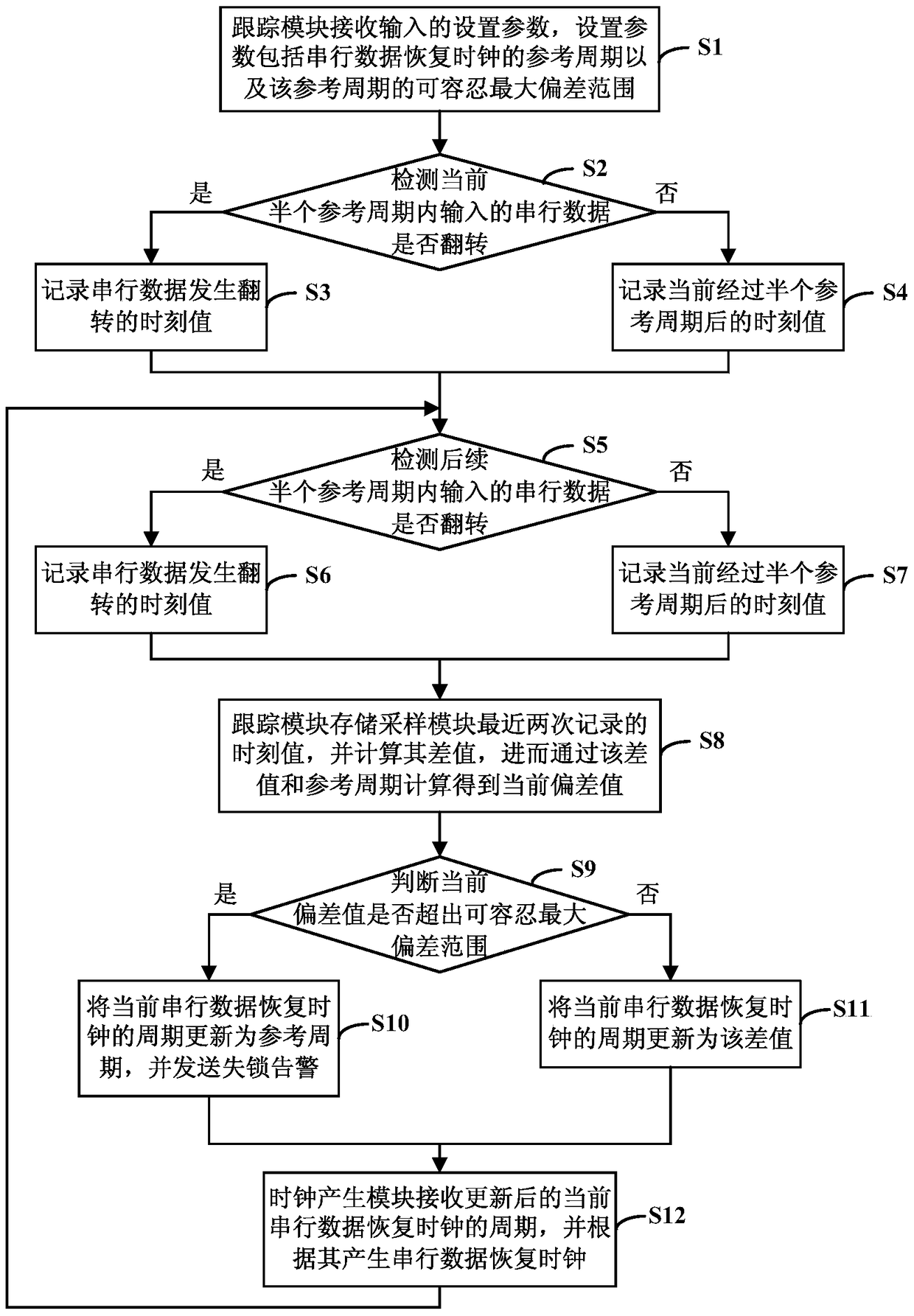
[0027] see figure 1 As shown, the embodiment of the present invention provides an efficient CDR verification system, including a sampling module, a tracking module and a clock generating module, wherein the sampling module is connected to the tracking module and the clock generating module, and the tracking module is connected to the clock generating module.

[0028] The sampling module is used to detect whether the input serial data is reversed in every half reference period, and record the time value at which the serial data is reversed or the current time value after half of the reference period has passed.

[0029] The tracking module is used to receive input setting parameters. The setting parameters include the reference period of the serial data recovery clock and the tolerable maximum deviation range of the reference period; the refere...


PUM


Abstract

The invention discloses efficient CDR validation model and method, and relates to the technical field of EDA validation. The efficient CDR validation model comprises a sampling module, a tracking module and a clock generation module, wherein the sampling module is used for detecting whether serial data input within each half reference cycle are turned over or not, and recording a moment value when the serial data are turned over or the moment value after the half reference cycle; the tracking module is used for receiving input setup parameters, wherein the setup parameters comprise a reference cycle of a serial data recovery clock and a tolerable maximum deviation range of the reference cycle; the tracking module is also used for storing the last two moment values which are recorded by the sampling module, calculating the difference value between the moment values, calculating the current deviation value according to the difference value and the reference cycle, and updating the cycle of the serial data recovery clock into the reference cycle or the difference value according to whether the current deviation value exceeds the tolerable maximum deviation range or not; and the clock generation module is used for receiving the updated cycle of the current serial data recovery clock and generating the serial data recovery clock according to the updated cycle.

Description

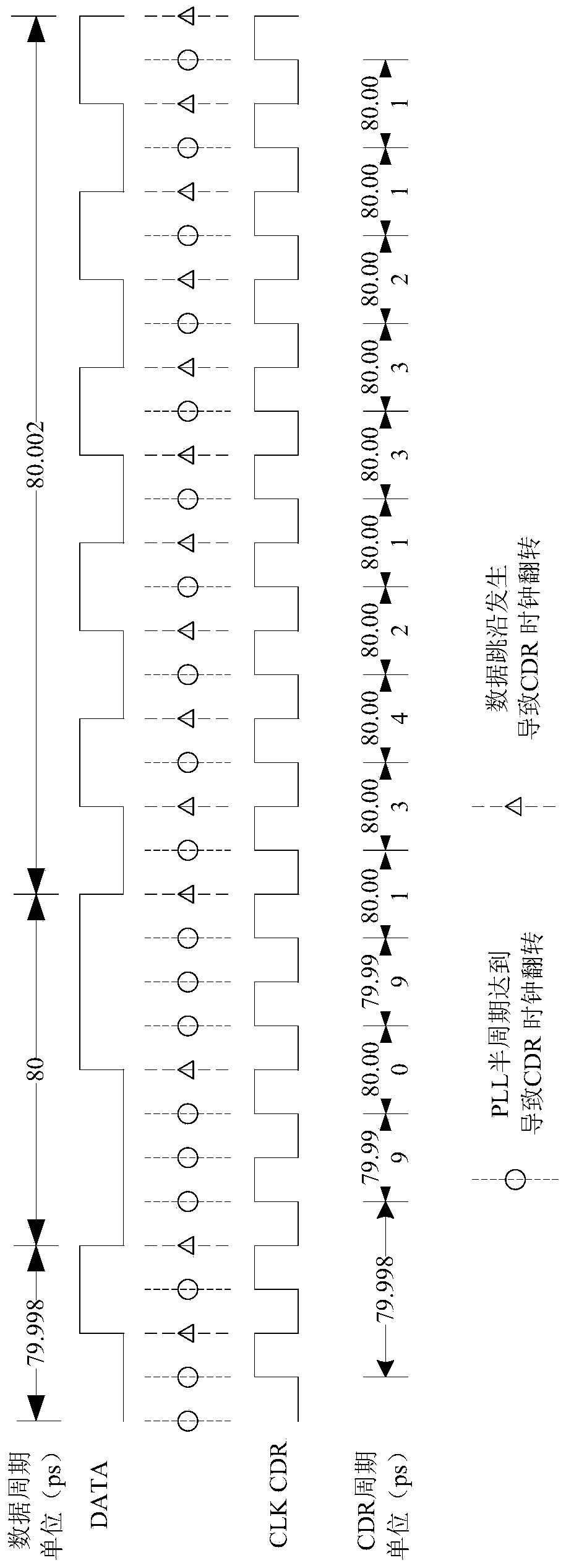
technical field [0001] The present invention relates to the field of EDA (Electronic Design Automation, electronic design automation) verification technology, specifically a highly efficient CDR (Clock and Data Recovery, clock data recovery) verification system and method. Background technique [0002] Network chips generally contain SerDes (SERializer / DESerializer, serializer), so the verification of network chips is inseparable from the simulation of the SerDes system. As we all know, the line side of the SerDes is serial data without a clock signal. The SerDes system will truly simulate the function of the actual SerDes. Therefore, the simulation environment needs to recover the clock from the serial data given by the SerDes system, so that the functional bus of the environment The system can collect data correctly. [0003] Since the period of the serial data output by the SerDes system is not constant and there is a swing, the SerDes serial data cannot be sampled with ...

Claims


Application Information

Patent Timeline
Patent Type & Authority Patents(China)
IPC IPC(8): G06F17/50
Inventor 张睿袁博浒
Owner 武汉二进制半导体有限公司
Learn More