Arc glass edge grinding machine

An edge grinding machine and glass technology, which is applied to machine tools, grinders, grinding workpiece supports and other directions suitable for grinding workpiece edges, can solve the problem of not realizing glass arc edge grinding processing, large working space, increasing energy consumption, etc. problems, to reduce pressure, improve safety, and prevent air leakage

Inactive Publication Date: 2015-12-23
SHENGZHOU HUANDING GLASS TECH CO LTD
View PDF1 Cites 17 Cited by
  • Summary
  • Abstract
  • Description
  • Claims
  • Application Information

AI Technical Summary

Problems solved by technology

[0003] The straight-line large chamfering glass edging machine (application number: 2013102329288, publication number: CN103273395, publication date: 2013.09.04) announced by the State Intellectual Property Office of China includes a frame, a feed drive motor mounted on the frame, a device The longitudinal guide rail on the frame and the worktable slidingly connected on the longitudinal guide rail, the power output end of the feed drive motor is connected with the feed screw parallel to the longitudinal guide rail, and the feed screw is threaded with the bottom of the workbench. One side of the longitudinal guide rail is equipped with an edge grinding device, and the workbench is equipped with a glass support block and a positioning and clamping device located around the glass support block, although the high-precision glass chamfering grinding process within the range of different angles is realized. , which reduces the cost and is easy to operate, but still only stays on the glass linear grinding process, and does not realize the arc edge grinding process of the glass, and the grinding machines in the prior art are all workbench movement, and the grinding mechanism Fixed, greatly increasing energy consumption, and need to occupy a larger working space

Method used


Image

  • Arc glass edge grinding machine
  • Arc glass edge grinding machine
  • Arc glass edge grinding machine

Examples


Embodiment Construction

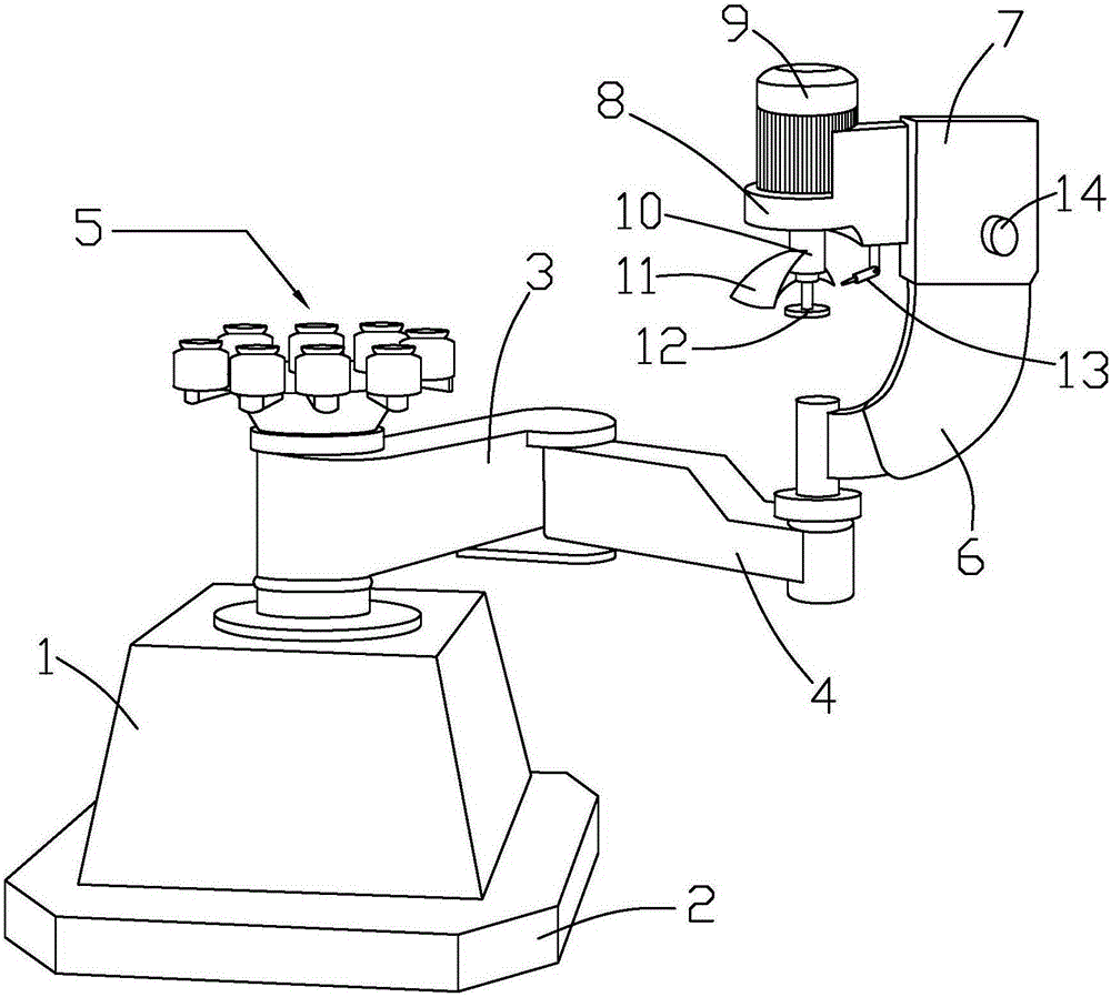
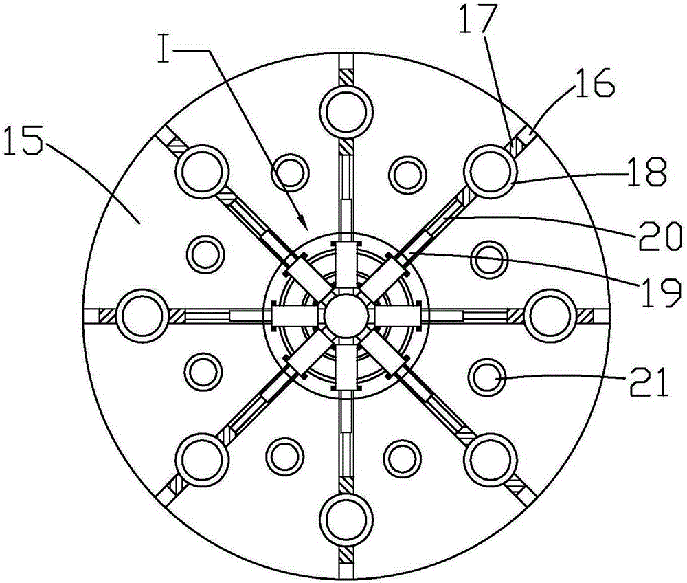
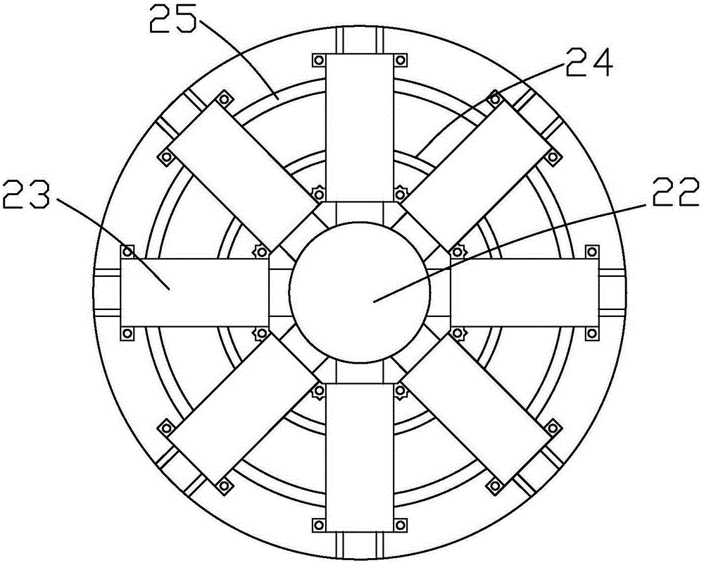
[0032] Such as Figure 1 to Figure 6 As shown, it is an arc glass edging machine of the present invention. The glass edging machine includes a box body 1, a positioning suction cup 5 and a grinding mechanism. Described casing 1, positioning sucker 5 comprise positioning chuck 15, main suction head 18 and auxiliary suction head 21, and the center of positioning chuck 15 is provided with through hole 22, and the periphery of through hole 22 is evenly provided with at least 8 guides. Groove 16, the main suction head 18 is limited in the guide groove 16 by the moving block 17, the top surface of the main suction head 18 is provided with a sealing ring 26, and the inside of the main suction head 18 is provided with a one-way sealing plate 27, adjacent up and down The two one-way sealing plates 27 are arranged in a staggered manner. When the glass is placed on the main suction head 18, the sealing ring 26 can effectively separate the air inside the main suction head 18 from the outsid...


PUM


Abstract

The invention discloses an arc glass edge grinding machine. The arc glass edge grinding machine comprises a box body, positioning suction cups and a grinding mechanism. The positioning suction cups are connected with the box body through a first cantilever. The other end of the first cantilever is connected with a second cantilever in a rotating manner. The end of the second cantilever is connected with a grinding mechanism. The grinding mechanism comprises an arc-shaped supporting frame, a fixed box, a positioning buckle plate and a first motor. The top end of the arc-shaped supporting frame is connected with the fixed box. The positioning buckle plate is arranged on the side face of the fixed box. The first motor is limited by the positioning buckle plate. A second motor, a hydraulic oil tank and a draught fan are arranged in the box body. An air inlet pipe and an air outlet pipe are arranged on the draught fan. The arc glass edge grinding machine is simple in structure and high in practicability, can conduct edge grinding on arc-shaped edges of conventional glass and can conduct arc edge grinding on glass of different sizes as well, the stability of glass during edge grinding is improved, glass uniformly bears force, the service life of the edge grinding machine is prolonged, and economic benefits are remarkable.

Description

technical field [0001] The invention relates to the technical field of glass processing, in particular to an arc glass edger. Background technique [0002] Glass edging machine is one of the earliest and most widely used mechanical equipment in glass deep processing equipment. Its main function is to smooth the glass and make some special shapes. It is generally used for grinding and polishing the bottom edge and chamfer of ordinary flat glass. . [0003] The straight-line large chamfering glass edging machine (application number: 2013102329288, publication number: CN103273395, publication date: 2013.09.04) announced by the State Intellectual Property Office of China includes a frame, a feed drive motor mounted on the frame, a device The longitudinal guide rail on the frame and the worktable slidingly connected on the longitudinal guide rail, the power output end of the feed drive motor is connected with the feed screw parallel to the longitudinal guide rail, and the feed s...

Claims


Application Information

Patent Timeline
Patent Type & Authority Applications(China)
IPC IPC(8): B24B9/10B24B41/06B24B55/04B24B55/02B24B27/00
CPCB24B9/10B24B27/0084B24B41/068B24B55/02B24B55/04
Inventor 应伟苹
Owner SHENGZHOU HUANDING GLASS TECH CO LTD
Why Eureka
Try Eureka