
Continuous rolling type airflow dyeing machine applied to clothing production

An airflow dyeing machine and pad dyeing technology, which is applied in the processing of textile materials, liquid/gas/vapor finished product processing, liquid/gas/vapor textile processing, etc., can solve uneven dyeing, increase fan power consumption, increase manufacturing Cost and other issues, to achieve the effect of simple machine structure, high degree of automation, smooth reciprocating motion

Active Publication Date: 2015-12-23
苏州盛泽科技创业园发展有限公司
View PDF6 Cites 3 Cited by
  • Summary
  • Abstract
  • Description
  • Claims
  • Application Information

AI Technical Summary

Problems solved by technology

[0003] At present, the airflow dyeing machine with traditional structure is mainly used in the market. This traditional dyeing machine uses a fan connected to the nozzle through a long pipe. Because the wind will generate a lot of energy loss when flowing in the pipe, As a result, the power consumption of the fan increases and a large amount of electricity is wasted
Another structure of the airflow dyeing machine is to equip each nozzle with a fan, so that the number of fans is the same as the number of nozzles. This improvement makes the structure of the airflow dyeing machine complicated, and accordingly increases the manufacturing cost and maintenance cost. In addition, one nozzle is equipped with one fan, which also results in low efficiency and waste of electric energy.
In addition, the airflow dyeing machine of the prior art dyes unevenly, resulting in a greatly increased defective rate

Method used


Image

  • Continuous rolling type airflow dyeing machine applied to clothing production
  • Continuous rolling type airflow dyeing machine applied to clothing production
  • Continuous rolling type airflow dyeing machine applied to clothing production

Examples


Embodiment Construction

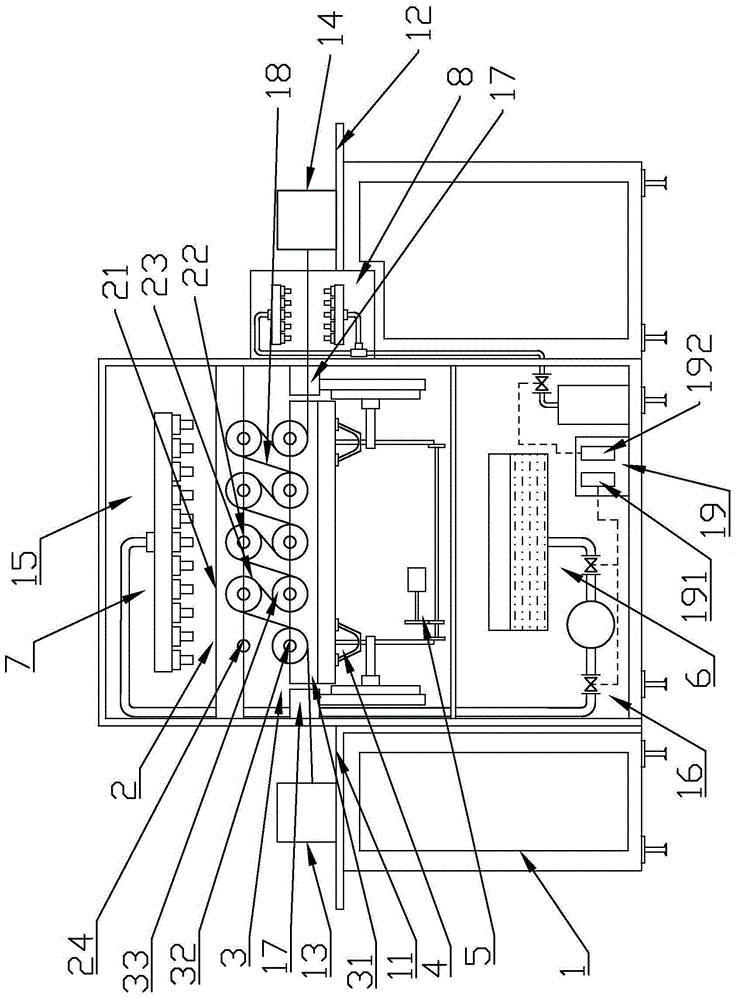
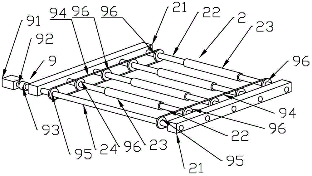
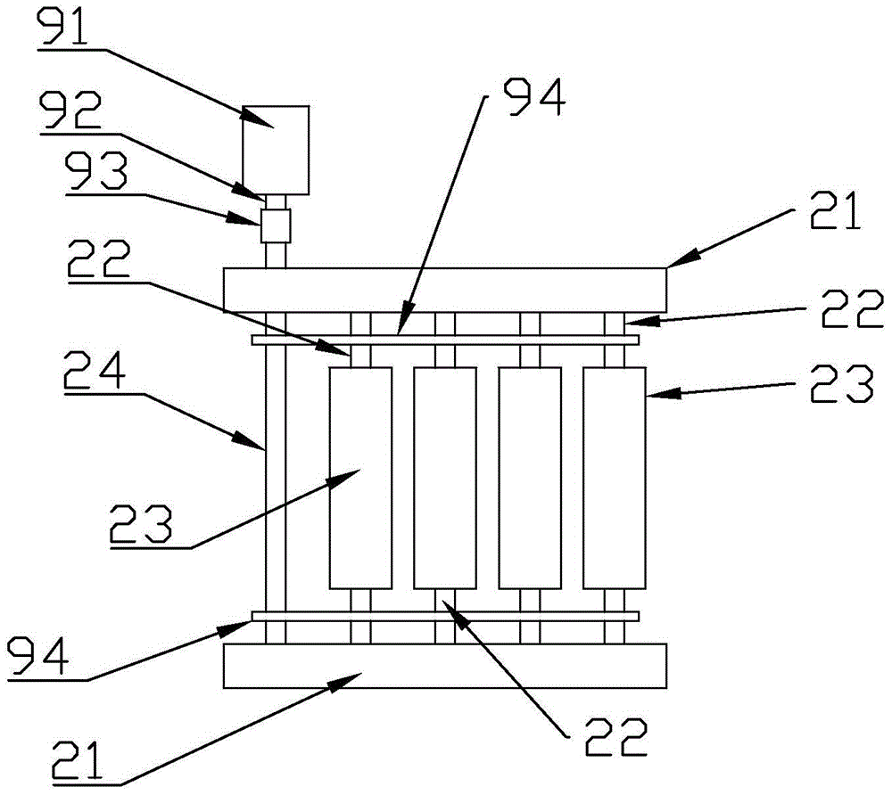
[0032] Such as Figure 1 to Figure 8 As shown, a continuous pad type airflow dyeing machine applied to garment production includes a frame 1 and a frame table, a dyeing chamber 15 and an airflow control chamber 16 are arranged in the middle of the frame 1, and the dyeing chamber 15 is located in the airflow control chamber 16 Above, the right side of dyeing chamber 15 is provided with heating device 8. The frame table top comprises the cloth feeding frame table top 11 and the cloth receiving frame table top 12, the cloth feeding frame table top 11 is provided with a cloth feeding frame 13, the cloth feeding frame 13 is provided with a dyeing cloth 18, and the cloth receiving frame table top 12 A cloth receiving frame 14 is provided, the cloth feeding frame 13 is positioned at the left side of the dyeing room 15, and the cloth receiving frame 14 is positioned at the right side of the dyeing room 15. A dyeing workbench 17 is arranged in the dyeing room 15, and a pad dyeing devi...


PUM


Abstract

The invention discloses a continuous rolling type airflow dyeing machine applied to clothing production. The continuous rolling type airflow dyeing machine comprises a rack and a rack table top. A drying chamber and an airflow control chamber are formed in the middle of the rack. A heating device is arranged at the right side of the dyeing chamber. A dyeing work table is arranged in the dyeing chamber and provided with a rolling and dyeing device. The rolling and dyeing device comprises an upper rolling and dyeing device and a lower rolling and dyeing device. The upper rolling and dyeing device is connected with the rolling and dyeing transmission device. A rolling and dyeing adjustment device is connected below the lower rolling and dyeing device and collected with an adjustment drive device. A control box and an airflow atomizing device are arranged in the airflow control chamber. The airflow atomizing device is connected with an airflow nozzle assembly located above the dyeing chamber. The machine is simple in structure, scientific, convenient, and high in pertinence and automation degree, and well solves the problem of dyeing cloth and fabric.

Description

technical field [0001] The invention relates to a continuous pad type airflow dyeing machine applied to garment production. Background technique [0002] Compared with the traditional liquid flow dyeing, the air-flow dyeing fabric is circulated by means of the air channel containing moisture or water vapor, without the need for dyeing liquid or water medium to transport the fabric, almost all fiber materials and their mixtures can be bleached and dyeing. The biggest feature is that it greatly reduces the consumption of dyes, chemical additives and energy. [0003] At present, the airflow dyeing machine with traditional structure is mainly used in the market. This traditional dyeing machine uses a fan connected to the nozzle through a long pipe. Because the wind will generate a lot of energy loss when flowing in the pipe, As a result, the power consumption of the fan increases and a large amount of electricity is wasted. Another structure of the airflow dyeing machine is t...

Claims


Application Information

Patent Timeline
Patent Type & Authority Applications(China)
IPC IPC(8): D06B3/18D06B3/30
Inventor 沈晨晖
Owner 苏州盛泽科技创业园发展有限公司
Learn More