
Engine exhaust system, air valve oil supply exhaust comprehensive control system and control method

An engine valve and exhaust system technology, applied in engine control, electrical control, engine components, etc., can solve the problems of reduced exhaust gas processor function, increased fuel injection volume of working cylinder, increased fuel injection time, etc. Longer service life, lower fuel consumption and lower emissions

Active Publication Date: 2015-12-23
牛刚学
View PDF5 Cites 7 Cited by
  • Summary
  • Abstract
  • Description
  • Claims
  • Application Information

AI Technical Summary

Problems solved by technology

Chinese patent 201310165338.8 proposes a technical solution for cylinder deactivation and oil cutoff of the engine, which makes the valve open while stopping the oil supply to the cylinder, but it is impossible to be adopted and implemented in reality, because The non-working valve is always open, and the fresh air entering the cylinder directly enters the exhaust pipe, which will distort the data detected by the sensor installed on the exhaust pipe, thereby sending a distorted signal to the ECU, causing the ECU to order oil supply The electromagnetic valve increases the fuel injection time, so that the fuel injection volume of the working cylinder is increased, and the combustion is very incomplete, resulting in waste of fuel and increased emissions of harmful substances
Another important thing is that a large amount of oxygen-enriched gas in the exhaust pipe will lead to the reduction or failure of the exhaust gas processor, causing the emission to seriously exceed the standard

Method used


Image

  • Engine exhaust system, air valve oil supply exhaust comprehensive control system and control method
  • Engine exhaust system, air valve oil supply exhaust comprehensive control system and control method
  • Engine exhaust system, air valve oil supply exhaust comprehensive control system and control method

Examples


Embodiment Construction

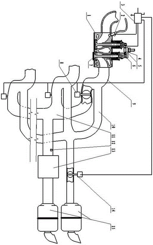
[0026] Such as figure 1 As shown, a kind of engine exhaust system, it comprises the exhaust manifold 9 that is connected with the air outlet of engine cylinder, a plurality of exhaust manifolds 9 are aggregated into exhaust pipe 11 and output through exhaust gas processor 13, muffler 15 , each exhaust manifold 9 is connected to the cylinder outlet in parallel with the exhaust branch pipe 10, and the outlet end of all exhaust branch pipes 10 is connected to the rear end of the exhaust gas processor 13; 9 is provided with an exhaust manifold valve 8, and the intake end of the exhaust manifold 10 is connected to the exhaust manifold 9 in front of the exhaust manifold valve 8; an exhaust manifold valve 14 is installed on the assembled exhaust manifold 10; A sensor 12 is installed on the exhaust pipe 11 ; the exhaust manifold valve 8 and the exhaust branch valve 14 are both connected to the control module 3 .

[0027] The control module 3 controls the functions of the engine, and ...


PUM


Abstract

The invention discloses an engine exhaust system, an air valve oil supply exhaust comprehensive control system and a control method. A valve is arranged on a double-path exhaust pipe composed of an exhaust pipe and an exhaust branch pipe, and an air valve starting mechanism enables an air valve to be in the starting state all the time; a control module integrates engine relevant data to comprehensively control an exhaust valve, an air valve starting mechanism and an oil supply electromagnetic valve, so that an engine has three excellent properties of pressure reduction starting, cylinder stop oil stopping and exhaust valve brake; oil consumption can be reduced, emissions are reduced, the service life of an engine and the service life of a starting system are prolonged, and the safety guarantee of an automobile in mountain driving is improved; and according to the scheme, the structure is simple, and the system is suitable for matching mounting of most engine types.

Description

technical field [0001] The invention relates to an engine exhaust system, an engine valve oil supply and exhaust comprehensive control system and a control method, which relate to the technical fields of engine valve control, oil circuit control and exhaust pipes. Background technique [0002] With the needs of sustainable development of human beings, it is required to protect nature, upgrade the technology of various energy consumption, and try to achieve low consumption, high efficiency and low emission. Specific to the engine, energy saving and emission reduction has become an inevitable requirement. At present, in engine energy-saving and emission-reduction technologies, one technology basically realizes one function, and the engine needs to be redesigned, which is costly. Furthermore, the consensus in the engine industry is that the energy saving and emission reduction of the engine are contradictory, and the actual situation is also like this. After realizing energy s...

Claims


Application Information

Patent Timeline
IPC IPC(8): F01N13/08F02D9/08F02D9/04F02D43/00F02D13/06F01L9/04F02D17/02F02B77/08F02D9/06F01L9/20F01L9/22
Inventor 牛刚学
Owner 牛刚学
Learn More