A multi-cylinder synchronous energy-saving and high-efficiency hydraulic lifting system and method

A hydraulic lifting and high-efficiency technology, applied in the field of lifting system, can solve the problems of large lateral force of hydraulic cylinder, unfavorable system stable operation, and large wear of elevator guide shoes and other parts, so as to achieve strong anti-eccentric load ability and improve anti-eccentric load Ability, low calorie effect

Inactive Publication Date: 2017-03-22
CHINA UNIV OF MINING & TECH
View PDF8 Cites 1 Cited by
  • Summary
  • Abstract
  • Description
  • Claims
  • Application Information

AI Technical Summary

Problems solved by technology

For these two methods, when the car is under partial load, the hydraulic cylinder is subject to a large lateral force, which will cause great wear to the elevator guide shoes and other parts, which is not conducive to the stable operation of the system.

Method used


Image

  • A multi-cylinder synchronous energy-saving and high-efficiency hydraulic lifting system and method
  • A multi-cylinder synchronous energy-saving and high-efficiency hydraulic lifting system and method
  • A multi-cylinder synchronous energy-saving and high-efficiency hydraulic lifting system and method

Examples


Embodiment 1

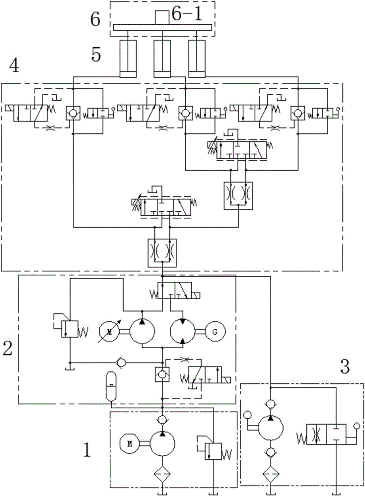
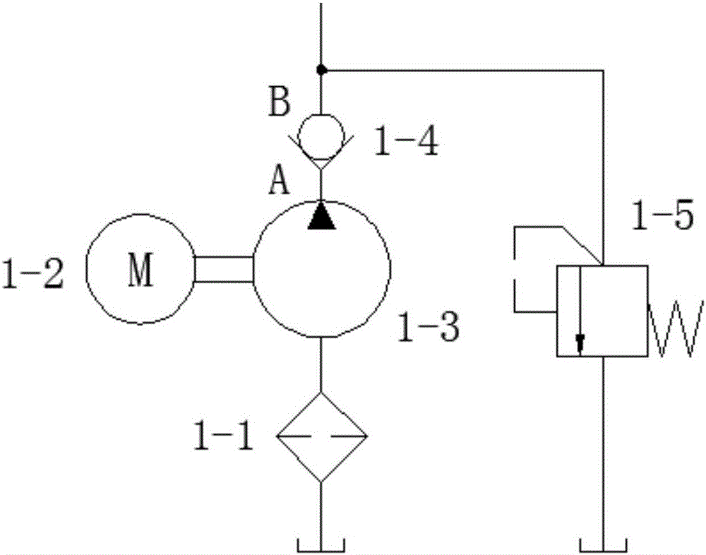
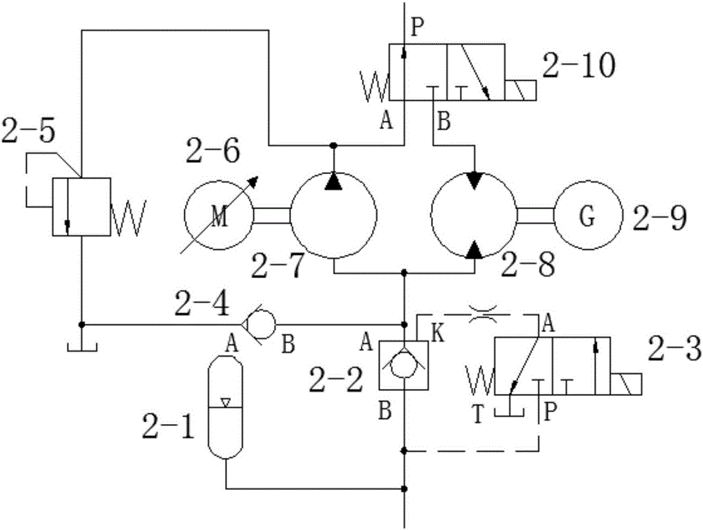
[0036] Embodiment 1, as figure 1As shown, the multi-cylinder synchronous energy-saving and high-efficiency hydraulic lifting system is mainly composed of oil supply circuit 1, volume speed regulation and energy recovery circuit 2, manual lifting circuit 3, synchronous locking circuit 4, hydraulic cylinder 5 supported under the lifting platform 6 and The inclination sensor 6-1 installed on the lifting platform 6 constitutes. The oil supply circuit 1 is connected to the volume speed regulation and energy recovery circuit 2 through pipelines, the volume speed regulation and energy recovery circuit 2, the manual lifting circuit 3 and the synchronous locking circuit 4 are connected to each other through pipelines, each A hydraulic cylinder 5 is connected with a locking circuit 4-3, and the locking circuit 4-3 is respectively connected with a diversion and flow valve 4-1 and an electro-hydraulic servo valve 4-2, and the locking circuit 4-3, the flow diversion and flow collection Th...

Embodiment 2

[0042] Embodiment 2 is basically the same as Embodiment 1, and the similarities are omitted. The difference is the synchronous locking circuit for driving two hydraulic cylinders 5 . Such as Figure 7 As shown, the synchronous locking circuit 4 that drives the three hydraulic cylinders includes a diverter-collector valve 4-1 with a split ratio of 1:1 connected to the inlet and outlet P of the lift electromagnetic reversing valve 2-10 through pipelines. The split port of the flow valve 4-1 is respectively connected with the electro-hydraulic servo valve 4-2 and the locking circuit 4-3, and the locking circuit 4-3 is connected with the rodless cavity of the corresponding hydraulic cylinder 5. Among them, after passing through the diverting and collecting valve 4-1 with a split ratio of 1:1, the oil is equally divided into two parts with roughly equal flow rates entering and leaving the locking circuit 4-3 and the hydraulic cylinder 5, and the electro-hydraulic servo valve is use...

Embodiment 3

[0043] Embodiment 3 is basically the same as Embodiment 1, the same points are omitted, and the difference is the synchronous locking circuit for driving four hydraulic cylinders. Such as Figure 8 As shown, the synchronous locking circuit 4 that drives four hydraulic cylinders includes a diversion-collection valve 4-1 with a split ratio of 1:1 connected to the inlet and outlet P of the lift electromagnetic reversing valve 2-10 through pipelines. The diversion outlet of the flow valve 4-1 is respectively connected with the electro-hydraulic servo valve 4-2 and two diversion-collection valves with a split ratio of 1:1. The locking circuit 4-3 is connected. The locking circuit 4-3 is connected with the rodless cavity of the corresponding hydraulic cylinder 5. Among them, after two diversions, the oil is divided into four equal flows into and out of the locking circuit 4-3 and hydraulic cylinder 5, and the electro-hydraulic servo valve is used to further adjust the flow in and ...


PUM


Abstract

A multi-cylinder synchronized hydraulic lifting / lowering system and method, applicable in lift systems such as a hydraulic elevator and a construction lifting / lowering platform. The system comprises a fluid replenishing circuit (1), a volumetric speed governing and energy recovery circuit (2), a manual lifting / lowering circuit (3), a synchronous locking circuit (4), a hydraulic cylinder (5), and a tilt angle sensor (6-1). The fluid replenishing circuit (1) is used for replenishing any shortage of a hydraulic fluid in a closed loop system caused by regulation of the synchronous locking circuit (4) and system leakage and reducing increases in the temperature of the hydraulic fluid. The volumetric speed governing and energy recovery circuit (2) provides the system with power, speed governing, and energy recovery. The function of the manual lifting / lowering circuit (3) is to manually lift / lower a platform when the system malfunctions. The function of the synchronous locking circuit (4) is to regulate multiple hydraulic cylinders for synchronized lifting / lowering and to lock tight the cylinders when the platform is stationary. The tilt angle sensor (6-1) detects in real-time the position and posture of the platform and feeds back to a control center, thus implementing closed loop control. The system is highly efficient and power saving and implements energy recovery and precise synchronization of multiple cylinders; the lifting / lowering platform has strong side-load resistance, operates steadily, and is high reliable.

Description

technical field [0001] The invention relates to a lifting system and method, in particular to a multi-cylinder synchronous energy-saving and high-efficiency hydraulic lifting system and method suitable for hydraulic elevators and construction lifting platforms. Background technique [0002] The driving methods of the lifting system mainly include traction type and hydraulic type. Hydraulic drive has the advantages of large output, stepless speed regulation, simple system, and convenient control, but the efficiency of hydraulic drive is lower than that of traction drive. "Green energy saving" is the future development goal of the system. At present, most hydraulic elevator systems adopt electro-hydraulic proportional control and volumetric speed control. Although the energy loss of the elevator going up is reduced, when the elevator goes down, the oil in the oil cylinder passes through the down throttle valve under the action of pressure. Cause the temperature rise of the h...

Claims


Application Information

Patent Timeline
Patent Type & Authority Patents(China)
IPC IPC(8): F15B11/22F15B1/02F15B21/14F15B13/06B66B11/04B66F11/04
CPCF15B11/22
Inventor 曹国华黄宇宏朱真才彭维红彭玉兴刘善增
Owner CHINA UNIV OF MINING & TECH
Why Eureka
Try Eureka