Worm and helical gear transmission pair based on variable pressure angle and application of worm and helical gear transmission pair

A technology of variable pressure angle and helical gears, which is applied to gear transmissions, transmissions, belts/chains/gears, etc., and can solve problems such as long processing cycles, different thicknesses of gears, and easy deformation of tooth shapes.

Pending Publication Date: 2015-12-23
SHENZHEN POWER MOTOR IND
View PDF0 Cites 8 Cited by
  • Summary
  • Abstract
  • Description
  • Claims
  • Application Information

AI Technical Summary

Problems solved by technology

[0005] 1. Gear injection molds require high precision, are difficult to manufacture, and have a long cycle time;
[0006] 2. Gear injection molding equipment, high precision requirements, strict process;
[0007] 3. The requirements for gear materials are high and the deformation needs to be small. Due to the different thickness of the gears, the tooth shape is easy to deform and the stability is poor.
[0008] We have conducted research on the above-mentioned technical problems for a long time. The method we currently adopt to solve the above-mentioned technical problems is in the metal worm and plastic helical gear transmission. Due to the different material properties and strengths of metal and plastic, we use tangential displacement The method is to reduce the thickness of the tooth profile of the worm, and increase the thickness of the tooth profi

Method used


Image

  • Worm and helical gear transmission pair based on variable pressure angle and application of worm and helical gear transmission pair
  • Worm and helical gear transmission pair based on variable pressure angle and application of worm and helical gear transmission pair
  • Worm and helical gear transmission pair based on variable pressure angle and application of worm and helical gear transmission pair

Examples


specific Embodiment approach

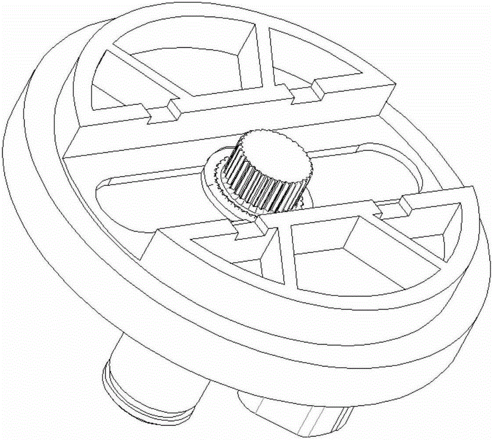
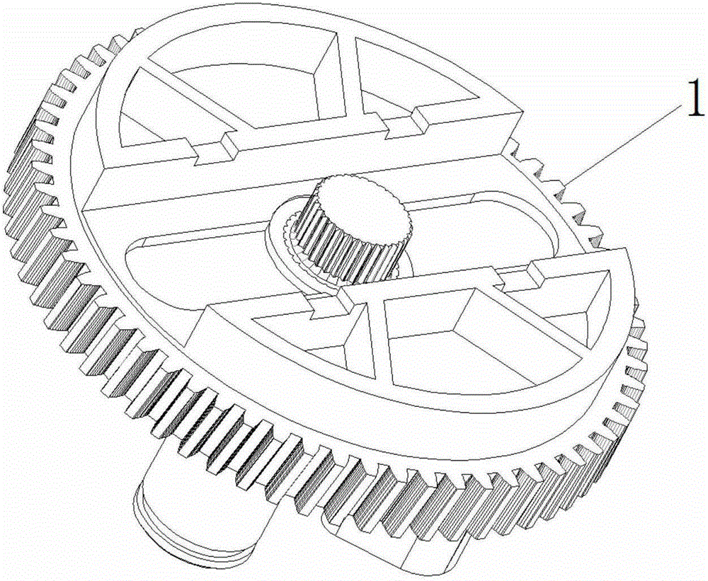
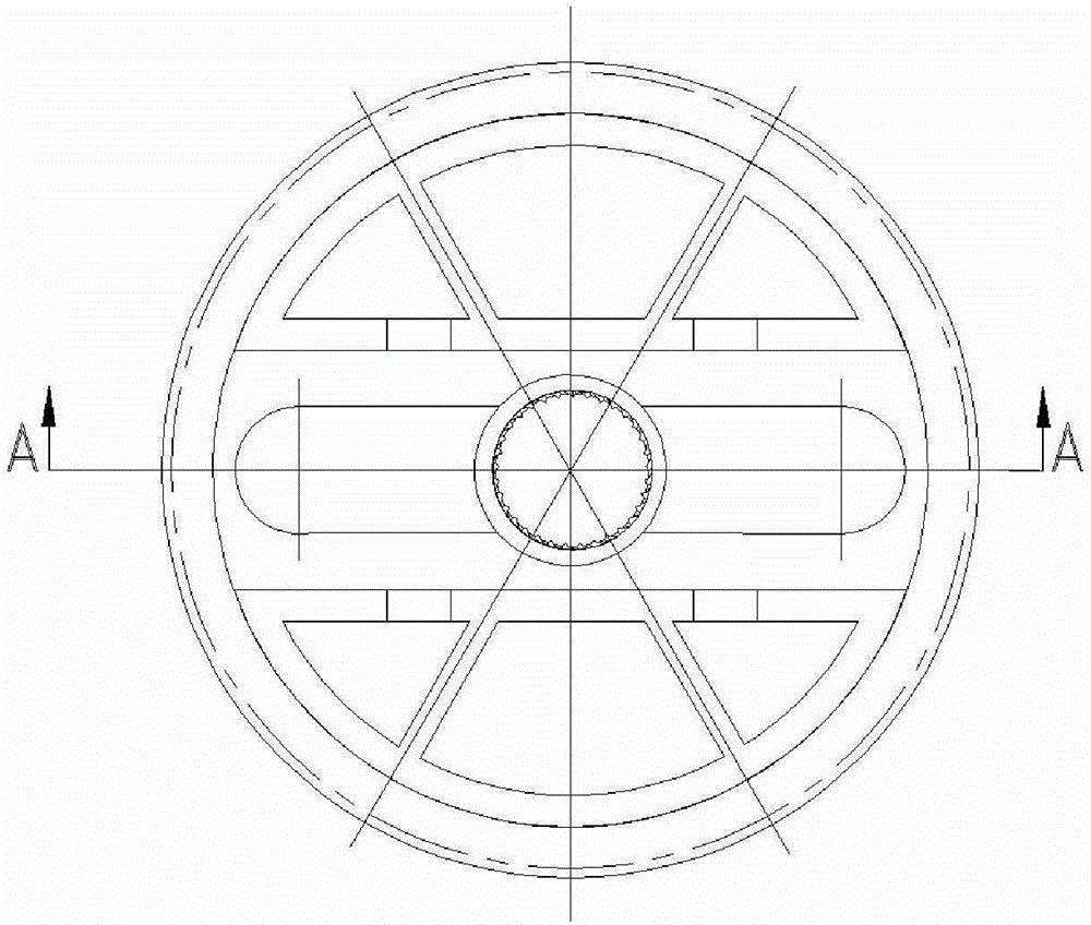
[0050] Such as Figure 1-7 Shown, it has shown the specific embodiment of the present invention, and the present invention is based on the worm helical gear transmission pair of variable pressure angle, comprises the worm screw and helical gear that meshes with each other; It is characterized in that:

[0051] Described helical gear end surface modulus (Mt2)=worm shaft surface modulus (Ma1);

[0052] Helical gear end face indexing scalloped angle (αn2) > worm shaft face indexing scalloped angle (αn1);

[0053] Helical gear indexing circle helix angle (β2) = worm shaft surface indexing circle lead angle (λ1);

[0054] The indexing crenated angle (αn2) on the end surface of the helical gear-the indexing crenated angle (αn1) on the worm shaft surface is less than 10°.

[0055] In some specific examples:

[0056]When, the helical gear end face modulus (Mt2)=worm shaft face modulus (Ma1); helical gear end face indexing crenated angle (αn2)=worm shaft face indexing crenated angle...


PUM

PropertyMeasurementUnit
Pitch circle diameteraaaaaaaaaa
Diameteraaaaaaaaaa
Diameteraaaaaaaaaa

Abstract

The invention discloses a worm and helical gear transmission pair based on a variable pressure angle and application of the worm and helical gear transmission pair. The worm and helical gear transmission pair is reliable in transmission, durable and easy to manufacture. In order to achieve the purposes, the worm and helical gear transmission pair based on the variable pressure angle comprises a worm and a helical gear which are engaged with each other, wherein the transverse module (Mt2) of the helical gear is equal to the shaft surface module (Ma1) of the worm; the tooth profile angle alpha n2 of the end face reference circle of the helical gear is larger than the tooth profile angle alpha n1 of the shaft surface reference circle of the worm; the swing angle beta 2 of the reference circle of the helical gear is equal to the lead angle lambda 1 of the shaft surface reference circle of the worm; the difference between the tooth profile angle alpha n2 of the end face reference circle of the helical gear and the tooth profile angle alpha n1 of the shaft surface reference circle of the worm is smaller than 10 degrees.

Description

technical field [0001] The invention relates to a worm helical gear transmission pair, in particular to a transmission pair in which a metal worm meshes with a plastic helical gear. Background technique [0002] Worm helical gear transmission has completely replaced worm gear transmission in occasions where the transmission contact surface is small (medium and light load) and transmission accuracy is not strictly required, and it is widely used in automobiles, kitchen appliances and other fields. Automotive motors (wiper wipers, window shakers, etc.) that use worm helical gear transmission require high quality reliability, low noise, long life and low cost, which has become the working direction of the enterprise; [0003] The traditional theory holds that: the correct meshing condition of worm and helical gear transmission is: Mt2 (helical gear end face modulus) = Ma1 (worm shaft face modulus); αt2 (helical gear end face indexing crenated angle) = αa1 (worm shaft β2 (helix...

Claims


Application Information

Patent Timeline
IPC IPC(8): F16H1/18F16H55/17F16H55/22B60S1/26
CPCF16H1/18B60S1/26F16H55/17F16H55/22
Inventor 陈坤桂刘延春肖泉
Owner SHENZHEN POWER MOTOR IND
Why Eureka
Try Eureka