Stress, strain or temperature abnormal area monitoring sensing element and manufacturing method thereof

A technology for sensing elements and abnormal areas, applied in the direction of measuring devices, instruments, etc., can solve the problems affecting the test accuracy, difficult temperature field measurement, application scope limitations, etc. simple structure

Inactive Publication Date: 2017-08-11
CHINA UNIV OF MINING & TECH
View PDF5 Cites 0 Cited by
  • Summary
  • Abstract
  • Description
  • Claims
  • Application Information

AI Technical Summary

Problems solved by technology

The contact test method mainly uses multi-point thermistors or thermocouples for testing. This method has limited layout, and each thermistor must be connected to the test line, which takes up a lot of space and affects the accuracy of the test. In terms of space constraints, environmental conditions and Under the influence of equipment requirements and other factors, it is difficult to achieve effective and feasible temperature field measurement
The indirect test method mainly includes acoustic and image processing measurement methods, among which the acoustic temperature measurement technology mainly calculates the temperature of the measured medium based on the principle that the propagation speed of sound waves in the medium changes with the change of the temperature of the passing medium. The method is affected by the medium composition, reconstruction algorithm accuracy, background noise, acoustic wave interference refraction, etc., and its application is often limited; the radiation temperature measurement technology of image processing is based on the functional relationship between the object's different spectral radiation intensities and temperatures. Because the radiation is affected by the scattering and attenuation coefficient of medium particles, the application range of this test method is limited

Method used


Image

  • Stress, strain or temperature abnormal area monitoring sensing element and manufacturing method thereof
  • Stress, strain or temperature abnormal area monitoring sensing element and manufacturing method thereof
  • Stress, strain or temperature abnormal area monitoring sensing element and manufacturing method thereof

Examples


Embodiment 1

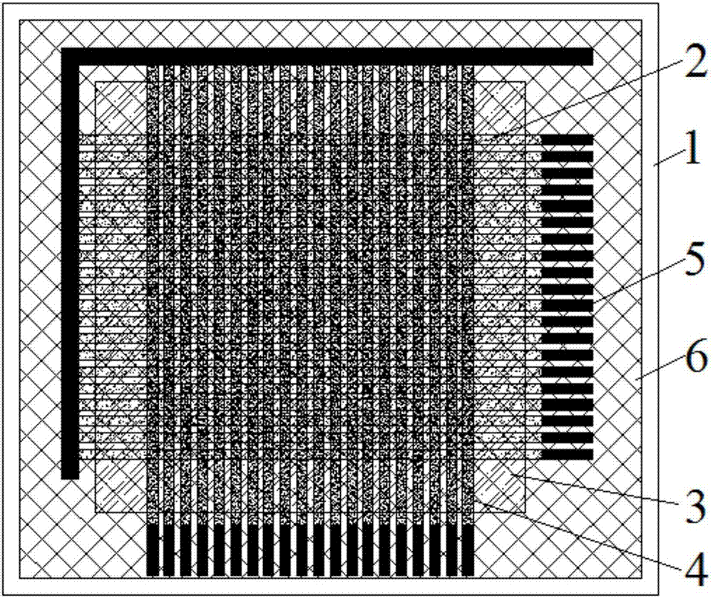
[0030] Embodiment 1: Assuming that the content to be monitored is a stress abnormal region in a plane field, it is relatively simple to initially determine the shape of the abnormal region. Such as figure 1 As shown, the basic composite layer structure of the sensor element for stress, strain or temperature anomaly monitoring in the plane field of the present invention includes a thin plate 1 of the first layer (bottom layer), a lateral arrangement of sensitive elements of the second layer 2, and a third layer of An insulating thin layer 3, a longitudinal array of sensitive elements 4 on the fourth layer, an electrode 5 on the fifth layer, and an insulating protective film 6 on the sixth layer (the uppermost layer). Since the monitoring content is the abnormal stress area in the plane field, the thin plate 1 is made of polyimide film with high compressive strength, the thickness is 0.1mm; the insulating material is epoxy resin, which is used for printing the insulating thin la...

Embodiment 2

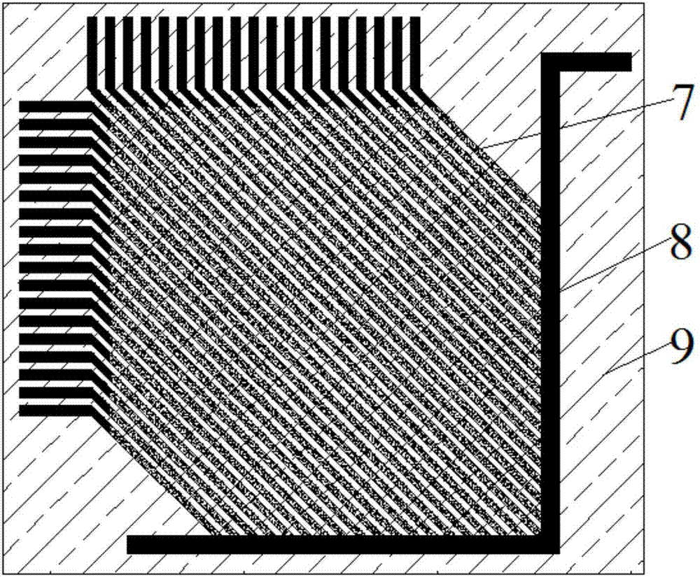
[0032] Embodiment 2: Assuming that the content to be monitored is an abnormal stress region in a plane field, the shape of the abnormal region is preliminarily judged to be complex. Such as figure 1 and figure 2 As shown, the stress, strain or temperature anomaly region monitoring sensor element in the plane field of the present invention includes a basic composite layer structure and an additional composite layer structure, wherein the basic composite layer structure includes a thin plate 1 of the first layer (bottom layer), a second layer Transverse array of sensitive elements 2, thin insulating layer 3 of the third layer, longitudinal array of sensitive elements 4 of the fourth layer, electrode 5 of the fifth layer and insulating protective film 6 of the sixth layer (uppermost layer); additional composite layer structure It includes a first layer (bottom layer) of sensitive element array 7 and electrodes 8 and a second layer (upper layer) of insulating protective film 9 ....

Embodiment 3

[0034] Embodiment 3: Assuming that the content to be monitored is an abnormal strain region in a plane field, it is relatively simple to initially determine the shape of the abnormal region. Such as figure 1 As shown, the basic composite layer structure of the sensor element for stress, strain or temperature anomaly monitoring in the plane field of the present invention includes a thin plate 1 of the first layer (bottom layer), a lateral arrangement of sensitive elements of the second layer 2, and a third layer of An insulating thin layer 3, a longitudinal array of sensitive elements 4 on the fourth layer, an electrode 5 on the fifth layer, and an insulating protective film 6 on the sixth layer (the uppermost layer). Since the monitoring content is the abnormal strain area in the plane field, the thin plate 1 uses a polyurethane film with high deformation resistance and a thickness of 0.1mm; the insulating material is silicon rubber, which is used to print the insulating thin ...


PUM


Abstract

A stress, strain or temperature abnormal area monitoring sensor element and its manufacturing method belong to the sensor element and its manufacturing method. There are basic composite layer structure and additional composite layer structure; the basic composite layer structure consists of a thin plate on the first layer, a horizontal arrangement of sensitive elements on the second layer, a thin insulating layer on the third layer, a longitudinal array of sensitive elements on the fourth layer, and a fifth layer The electrode of the first layer and the insulating protective film of the sixth layer; the additional composite layer structure layer is composed of the sensitive element array and electrode of the first layer and the insulating protective film of the second layer, which can be added on the basic composite layer structure as required. The sensing element can realize the monitoring of abnormal stress area, abnormal strain area or abnormal temperature area in the two-dimensional plane field, depending on the selection of the sensitive element. When monitoring the abnormal strain area, it is necessary to select a sensitive material with better strain sensitivity. Sensitive element array. The invention has a simple and effective structure; adopts a silk screen printing process, the method is simple and reliable, and the cost is low.

Description

technical field [0001] The invention relates to a sensing element and a manufacturing method thereof, in particular to a stress, strain or temperature abnormal region monitoring sensing element and a manufacturing method thereof. Background technique [0002] At present, the method used for two-dimensional plane stress field monitoring mainly includes the method of thin-film pressure distribution sensor. Compared with the traditional method of multi-point distribution of pressure cells, this method has certain progress, but this kind of sensor is more expensive. The methods used for two-dimensional plane strain field testing mainly include contact measurement method and non-contact measurement method. Among them, the contact measurement method mainly uses multi-point resistive strain gauges for testing. This method has limited layout and large strain gauge size. In addition, each strain gauge has to be connected to the test line, which takes up a lot of space and affects the...

Claims


Application Information

Patent Timeline
Patent Type & Authority Patents(China)
IPC IPC(8): G01D21/02
Inventor 周国庆廖波梁恒昌王义江季雨坤常传源周檀君
Owner CHINA UNIV OF MINING & TECH
Why Eureka
Try Eureka