A monitoring device and monitoring method for soil carbon dioxide concentration

A carbon dioxide and monitoring device technology, applied in the field of karst research, can solve the problems of difficult drilling, large soil disturbance, low precision, etc., and achieve the effects of rapid response, no reagent consumables, and high precision

Inactive Publication Date: 2017-08-29
INST OF KARST GEOLOGY CAGS
View PDF8 Cites 2 Cited by
  • Summary
  • Abstract
  • Description
  • Claims
  • Application Information

AI Technical Summary

Problems solved by technology

The above research methods have the following defects: (1) The disturbance to the soil is too large. Even if the backfilling is strictly in accordance with the undisturbed soil 2, the composition and porosity of the newly backfilled part of the soil will be very different from the undisturbed soil. When the runoff 3 is generated, the surface runoff 3 will preferentially flow into the soil layer from the interface 5 between the undisturbed soil 2 and the backfill soil 4, which is similar to pipeline flow, rather than uniform infiltration, which greatly reduces the representativeness of the monitoring results
The defect of this method mainly contains: (1) in the hammer drilling process, the steel drill 10 has a compacting effect on the soil around the hole wall, and the pores around the hole wall are closed; in the dry season, the soil moisture content is low (2) When detecting the concentration of carbon dioxide, since only the vicinity of the hole is closed, under the action of vacuum, the gas in the entire hole, and even the gas in the soil layers at various depths may Entering the detection tube, the test result is the concentration of the mixed gas, which cannot truly represent the soil carbon dioxide concentration at a specific depth; (3) The consumption of detection tube consumables is large; (4) The reading is manually interpreted according to the degree of discoloration of the reagent, and the error is large big, small precision

Method used


Image

  • A monitoring device and monitoring method for soil carbon dioxide concentration
  • A monitoring device and monitoring method for soil carbon dioxide concentration
  • A monitoring device and monitoring method for soil carbon dioxide concentration

Examples


Embodiment Construction

[0026] The principles and features of the present invention are described below in conjunction with the accompanying drawings, and the examples given are only used to explain the present invention, and are not intended to limit the scope of the present invention.

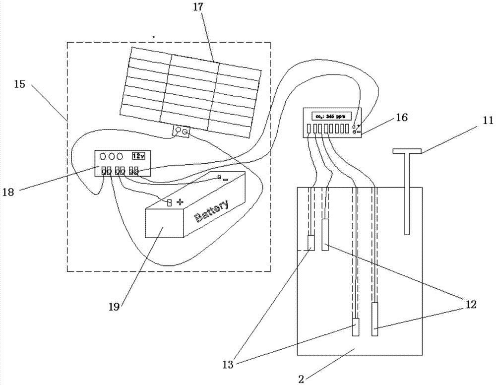
[0027] like image 3 As shown, a monitoring device for soil carbon dioxide concentration includes a drill bit 11, a carbon dioxide concentration probe 12, a temperature and humidity probe 13, a power supply module 15 and a data collector 16, and the drill bit 11 drills out and embeds the carbon dioxide in the soil respectively. Concentration probe 12 and the drilling holes of the temperature and humidity probe 13 , the diameter of the drill bit 11 is larger than the diameters of the carbon dioxide concentration probe 12 and the temperature and humidity probe 13 . The drill bit 11 is provided with a length scale. According to the depth of the soil to be monitored from the surface, the depth of the drill bit 11 can be...


PUM

PropertyMeasurementUnit
diameteraaaaaaaaaa

Abstract

The invention relates to a soil carbon dioxide concentration monitoring device and method. The soil carbon dioxide concentration monitoring device comprises drill bits, carbon dioxide concentration probes, temperature and humidity probes, a power supply module and a data acquisition unit. The drill bits drill out drill holes for burying the carbon dioxide concentration probes and the temperature and humidity probes respectively in soil. The data acquisition unit is connected with the carbon dioxide concentration probes and the temperature and humidity probes through data lines, and the monitoring data of the carbon dioxide concentration probes and the temperature and humidity probes are preserved. The power supply module is connected with the carbon dioxide concentration probes, the temperature and humidity probes and the data acquisition unit through wires. The soil carbon dioxide concentration monitoring device and method have the advantages that monitoring data are accurate and stable, disturbance to soil is lowered to the minimum, the soil carbon dioxide concentration of a certain depth can be monitored, the probes are protected, influences on monitoring of continuous rainfall are avoided, the soil carbon dioxide concentration monitoring device can conduct soil monitoring continuously in tropical regions and subtropical regions for a long time, a display meter is added, power is supplied through batteries, the soil carbon dioxide concentration can be fast measured outdoors, and the soil carbon dioxide concentration monitoring device has the advantages of being quick in response, high in accuracy, free of reagent supply and the like.

Description

technical field [0001] The invention relates to the field of karst research, in particular to a monitoring device and a monitoring method for soil carbon dioxide concentration. Background technique [0002] like figure 1 As shown, in the previous studies on the carbon dioxide concentration gradient of soil at different depths, due to the limitation of technical means, the probe 1 buried in the soil was extremely vulnerable to the influence of soil moisture and was scrapped, resulting in interruption of monitoring (due to continuous rainfall in the rainy season after 14 hours). , the moisture content of the soil rises and even reaches saturation, which makes the probe 1 directly soaked in water, resulting in an internal short circuit of the probe). Moreover, the method of direct excavation is adopted when installing the probe 1: that is, at the place where the probe 1 needs to be installed, the plants and litter on the ground surface are removed, and then the soil is removed...

Claims


Application Information

Patent Timeline
Patent Type & Authority Patents(China)
IPC IPC(8): G01N33/24
Inventor 汪进良章程苗迎郝玉培
Owner INST OF KARST GEOLOGY CAGS
Why Eureka
Try Eureka