Design method for damping coefficient of end longitudinal shock absorbers of high-speed railway vehicle body

A technology of longitudinal, high-speed rail at the end, applied in the directions of instruments, calculations, mechanical equipment, etc., can solve problems such as theoretical design methods without a given system, and difficulties in dynamic analysis and calculation.

Inactive Publication Date: 2015-12-23
SHANDONG UNIV OF TECH
View PDF2 Cites 2 Cited by
  • Summary
  • Abstract
  • Description
  • Claims
  • Application Information

AI Technical Summary

Problems solved by technology

However, according to the information obtained, it is very difficult to analyze and calculate the dynamics of the rail vehicle because it belongs to a multi-degree-of-freedom vibration system. Most of the theoretical design methods of the system rely on computer technology and use multi-body dynamics simulation software SIMPACK or ADAMS / Rail to optimize and determine its size through solid modeling. Although this method can obtain relatively reliable simulation values, the vehicle has Better dynamic performance, however, with the continuous increase of the speed of rail vehicles, people have put forward higher requirements for the design of the damping coefficient of the longitudinal shock absorber at the end of the car body. At present, the damping coefficient of the longitudinal shock absorber at the end of the car body The design method cannot give a guiding innovation theory, and cannot meet the development of shock absorber design requirements under the condition of continuous speed increase of rail vehicles

Method used


Image

  • Design method for damping coefficient of end longitudinal shock absorbers of high-speed railway vehicle body
  • Design method for damping coefficient of end longitudinal shock absorbers of high-speed railway vehicle body
  • Design method for damping coefficient of end longitudinal shock absorbers of high-speed railway vehicle body

Examples


Embodiment Construction

[0029] specific implementation plan

[0030] The present invention will be further described in detail through an embodiment below.

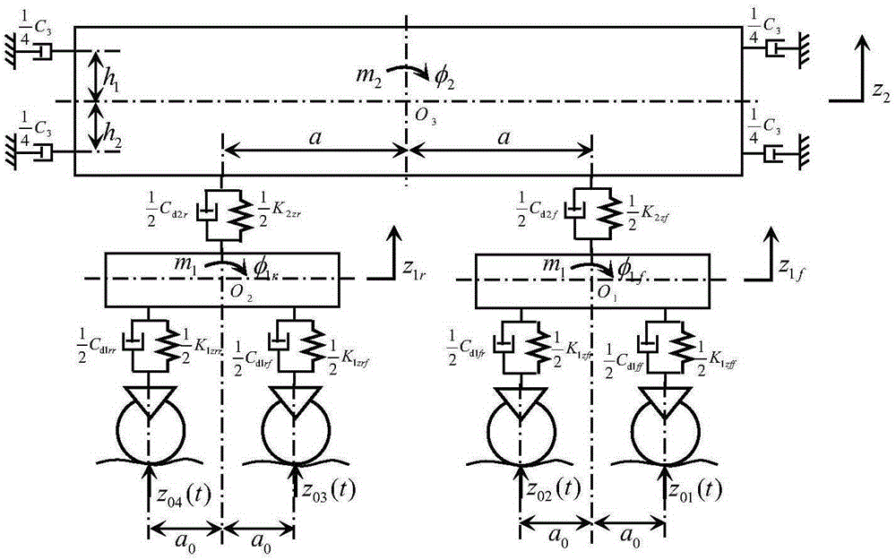
[0031] Four longitudinal shock absorbers at the end of the car body are installed between two adjacent car bodies of a high-speed rail vehicle, that is, n=4, and the mass of a single car body is m 2 =63966kg, nodding moment of inertia J 2φ =2887500kg.m 2 ; Mass of each bogie frame m 1 =2758kg, nodding moment of inertia J 1φ =2222kg.m 2 ;The vertical equivalent stiffness K of the front suspension of the front bogie1zff =2.74×10 6 N / m, vertical equivalent damping C d1ff =28.3kN.s / m, the vertical equivalent stiffness K of the primary rear suspension of the front bogie 1zfr =2.74×10 6 N / m, vertical equivalent damping C d1fr =28.3kN.s / m; The vertical equivalent stiffness K of the primary front suspension of the rear bogie 1zrf =2.74×10 6 N / m, vertical equivalent damping C d1rf =28.3kN.s / m, the vertical equivalent stiffness K of the primar...


PUM


Abstract

The invention relates to a design method for the damping coefficient of end longitudinal shock absorbers of a high-speed railway vehicle body, and belongs to the technical field of high-speed railway vehicle suspension. Through establishing a six-freedom-degree vertical vibration optimal design simulation model of a whole railway vehicle, with railway vertical irregularity being input excitation and the minimum root-mean-square value of vibration acceleration of vehicle body bounce movement being a design target, the optimal damping coefficient of the end longitudinal shock absorbers of the vehicle body is obtained through optimal design. Through a design example and SIMPACK simulation verification, the accurate and reliable damping coefficient value of the end longitudinal shock absorbers of the vehicle body can be obtained through the method, and the reliable design method is provided for the design of the damping coefficient of the end longitudinal shock absorbers of the high-speed railway vehicle body. By the utilization of the method, the design level of a high-speed railway vehicle suspension system can be increased, and the driving safety and stability of the vehicle are improved; meanwhile, the product design and test costs can be lowered, so that the international market competitiveness of the railway vehicle in China is enhanced.

Description

technical field [0001] The invention relates to a high-speed rail vehicle mount, in particular to a design method for the damping coefficient of a longitudinal shock absorber at the end of a high-speed rail vehicle body. Background technique [0002] The longitudinal shock absorber at the end of the car body is installed between two adjacent car ends of an articulated or bogie-type high-speed rail vehicle, which can effectively attenuate the longitudinal vibration of the car body and significantly increase the integrity and stability of the vehicle. However, according to the information obtained, it is very difficult to analyze and calculate the dynamics of the rail vehicle because it belongs to a multi-degree-of-freedom vibration system. Most of the theoretical design methods of the system rely on computer technology and use multi-body dynamics simulation software SIMPACK or ADAMS / Rail to optimize and determine its size through solid modeling. Although this method can obtai...

Claims


Application Information

Patent Timeline
Patent Type & Authority Applications(China)
IPC IPC(8): G06F17/50
CPCY02T10/40
Inventor 周长城于曰伟赵雷雷
Owner SHANDONG UNIV OF TECH
Why Eureka
Try Eureka