Full ceramic type covering fuel particle, preparation method of full ceramic type covering fuel particle and fuel element
A technology for coating fuel particles and fuel elements, which is applied to fuel elements, reactor fuel materials, and manufacturing reactors, etc., can solve problems such as corrosion and oxidation, and achieve the effect of simple process flow, convenient process operation, and industrialized mass production.
- Summary
- Abstract
- Description
- Claims
- Application Information
AI Technical Summary
Problems solved by technology
Method used
Image
Examples
Embodiment 1
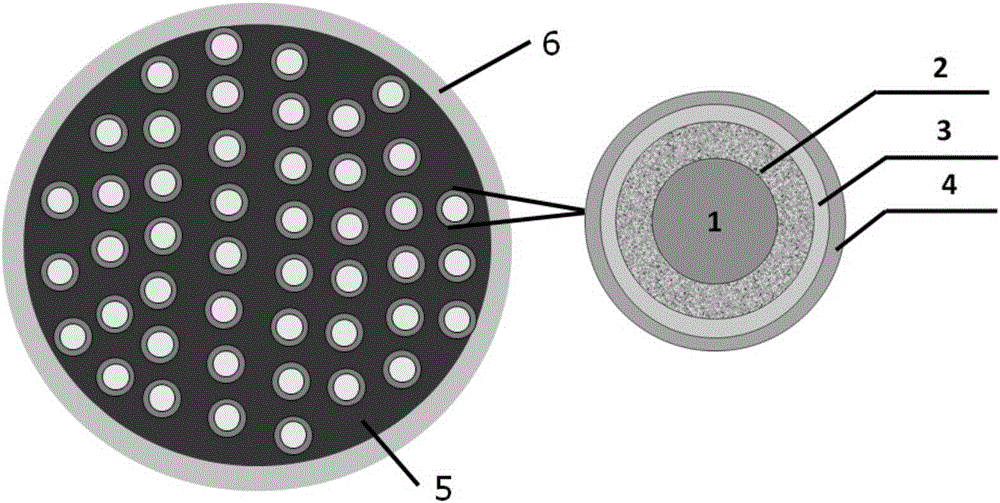
[0036] This embodiment relates to a coated fuel particle, which uses ceramic fuel as the core, and sequentially coats a loose silicon carbide layer, a silicon carbide transition layer and a dense silicon carbide layer on the outside of the core.
[0037] The material composition of the ceramic fuel core is uranium dioxide, and the diameter is 500-600 μm.
[0038] The loose silicon carbide layer is made of methyltrichlorosilane with a density of 1.40g / cm 3 , with a thickness of 90-100 μm.
[0039] The silicon carbide transition layer is made of methyltrichlorosilane with a density of 2.60g / cm 3 , with a thickness of 10-15 μm.
[0040] The dense silicon carbide layer is made of methyltrichlorosilane with a density of 3.20g / cm 3 , with a thickness of 40-50 μm.
Embodiment 2
[0042] This embodiment relates to a coated fuel particle, with ceramic fuel as the core, and a loose silicon carbide layer, a silicon carbide transition layer and a dense silicon carbide layer that are sequentially coated on the outside of the core.
[0043] The material composition of the ceramic fuel core is a mixture of uranium dioxide and uranium carbide, and the ceramic core is a sphere with a diameter of 700-800 μm;
[0044] The loose silicon carbide layer is made of hexamethyldisilane with a density of 1.80g / cm 3 , with a thickness of 60-80 μm.
[0045] The silicon carbide transition layer is made of hexamethyldisilane with a density of 2.60 g / cm 3 , with a thickness of 10-15 μm.
[0046] The dense silicon carbide layer is made of hexamethyldisilane with a density of 3.18g / cm 3 , with a thickness of 30-40 μm.
Embodiment 3
[0048] This embodiment relates to a coated fuel particle, with ceramic fuel as the core, and a loose silicon carbide layer, a silicon carbide transition layer and a dense silicon carbide layer that are sequentially coated on the outside of the core.
[0049] The material composition of the ceramic fuel core is a mixture of uranium dioxide and uranium carbide, and the ceramic core is a sphere with a diameter of 500-600 μm;
[0050] The loose silicon carbide layer is made of methyltrichlorosilane with a density of 2.00g / cm 3 , with a thickness of 70-90 μm.
[0051] The silicon carbide transition layer is made of methyltrichlorosilane with a density of 2.70g / cm 3 , with a thickness of 15-25 μm.
[0052] The dense silicon carbide layer is made of methyltrichlorosilane with a density of 3.20g / cm 3 , with a thickness of 50-60 μm.
PUM
| Property | Measurement | Unit |
|---|---|---|
| Density | aaaaa | aaaaa |
| Thickness | aaaaa | aaaaa |
| Density | aaaaa | aaaaa |
Abstract
Description
Claims
Application Information
 - R&D
- Intellectual Property
- Life Sciences
- Materials
- Tech Scout
- Unparalleled Data Quality
- Higher Quality Content
- 60% Fewer Hallucinations
Browse by: Latest US Patents, China's latest patents, Technical Efficacy Thesaurus, Application Domain, Technology Topic, Popular Technical Reports.
© 2025 PatSnap. All rights reserved.Legal|Privacy policy|Modern Slavery Act Transparency Statement|Sitemap|About US| Contact US: help@patsnap.com


