
Wind/solar hybrid generation control method and system with function of reactive self-compensation

A technology of wind-solar hybrid power generation and wind power generation system, which is applied in reactive power compensation, reactive power adjustment/elimination/compensation, photovoltaic power generation, etc., and can solve problems such as underutilized resources, underutilized power, idle power of power conversion devices, etc.

Active Publication Date: 2015-12-23
CEEC HUNAN ELECTRIC POWER DESIGN INST +1
View PDF4 Cites 12 Cited by
  • Summary
  • Abstract
  • Description
  • Claims
  • Application Information

AI Technical Summary

Problems solved by technology

At present, the wind-solar hybrid power generation system mainly has the following deficiencies: 1. Simply connecting the two resources together does not make full use of the characteristics of the two energy sources to maximize the power generation efficiency of the two power generation equipment at the same time; 2. The wind turbine manufacturer And the photovoltaic inverter manufacturer only considers its own output power, and does not consider the maximum output power comprehensively from the perspective of the entire system; 3. Due to the actual situation, most of the working conditions of the fan and photovoltaic inverter do not reach full load running, the power conversion device has a certain power idle, and the resources are not fully utilized

Method used


Image

  • Wind/solar hybrid generation control method and system with function of reactive self-compensation
  • Wind/solar hybrid generation control method and system with function of reactive self-compensation
  • Wind/solar hybrid generation control method and system with function of reactive self-compensation

Examples


Embodiment Construction

[0065] The present invention will be further described below in conjunction with the accompanying drawings and embodiments.

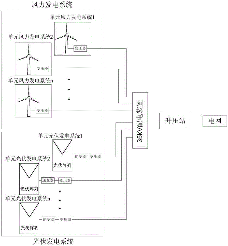
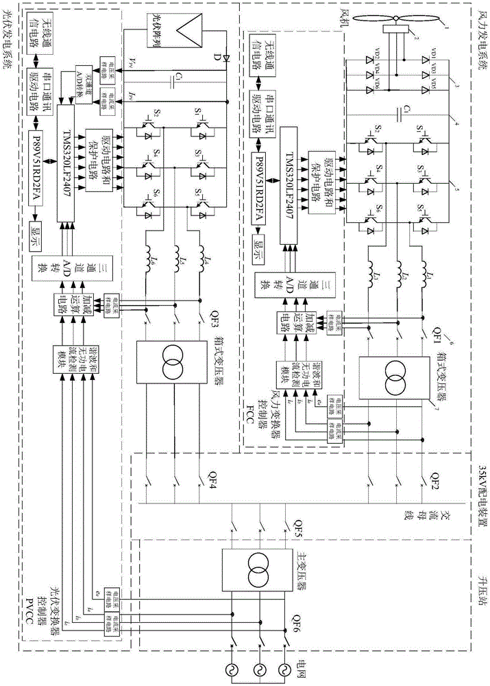
[0066] A control method for wind and solar hybrid power generation with reactive power self-compensation. The wind power generation system and the photovoltaic power generation system are connected to the 35kV power distribution device through a circuit breaker, and the 35kV power distribution device is connected to the power grid through a booster station. The reactive power consumption of its own generator and wind power box-type transformer is compensated, and the photovoltaic power generation system is used to compensate the reactive power consumption of the step-up station and the photovoltaic box-type transformer. The control process includes the following steps:

[0067] Step 1: Use the control unit of the photovoltaic power generation system to collect the voltage and current signals of the main transformer outlet side of the step-up station and ...


PUM


Abstract

The invention discloses a wind / solar hybrid generation control method and system with a function of reactive self-compensation. The method employs a method of reactive signal averaging, and employs the coordination of a plurality of photovoltaic power generation units at a wind / solar hybrid generation station for active / reactive control. A wind power generation unit outputs electric energy, and the quality of electric energy is solved at a high-voltage side of a draught fan box-type transformer. The photovoltaic power generation units achieve the active / reactive regulation of the whole power station. Reactive power compensated by a photovoltaic array is uniformly distributed to each unit photovoltaic power generation system. Each device of the whole power generation system is used reasonably, thereby achieving the reactive self-compensation of a wind / solar hybrid generation system, and achieve a purpose of maximizing benefits in a life cycle of the devices. The system makes the most of characteristics of two types of energy, reasonably uses each device of the system from the aspect of the whole power generation system, achieves the purpose of maximizing benefits in the life cycle of the devices, saves a dedicated reactive compensation device, reduces the initial investment, and improves the utilization rate of devices.

Description

technical field [0001] The invention belongs to the field of reactive power compensation in power generation and photovoltaic power generation, and particularly relates to a control method and system for wind and solar complementary power generation with reactive power self-compensation. Background technique [0002] Wind energy and solar energy are non-polluting, inexhaustible renewable energy sources. At present, there are many existing and under construction wind farms and photovoltaic power stations in my country. Both forms of power generation have their own advantages, but both wind and solar are unstable, discontinuous sources of energy. my country belongs to the monsoon climate zone. Generally, the winter monsoon is strong and the solar radiation intensity is small; the summer monsoon is small and the solar radiation intensity is high. The two energy sources can just complement each other. The wind-solar hybrid power generation system has many advantages: using the...

Claims


Application Information

Patent Timeline
Patent Type & Authority Applications(China)
IPC IPC(8): H02S10/12H02J3/18
CPCY02E40/30Y02E10/56Y02E10/76
Inventor 刘思佳宁秀元刘晓莲戴秋华喻镇廷王红才朱赞锋
Owner CEEC HUNAN ELECTRIC POWER DESIGN INST
Learn More