
Method for sensing current in a conductor

A technology of conductors and conductive traces, which is applied in the direction of measuring electrical variables, periodic selective voltage/current level measurement, voltage/current isolation, etc., and can solve problems such as large volume, maximum circuit density limitation, and reduced lifespan.

Active Publication Date: 2015-12-23
DEERE & CO
View PDF12 Cites 7 Cited by
  • Summary
  • Abstract
  • Description
  • Claims
  • Application Information

AI Technical Summary

Problems solved by technology

Other prior art sensors for sensing current in conductors can occupy a larger volume than desired because the maximum circuit density can be limited while efficiently handling thermal stress
But other prior art sensors may not respond adequately to rapid changes in current; thus, failing to respond to a sudden short circuit at the output of the inverter
Thus, there is a need for small sensors for sensing current that are resistant to reduced lifetime or failure associated with thermal stress or with inaccurate sensing of rapidly changing currents

Method used


Image

  • Method for sensing current in a conductor
  • Method for sensing current in a conductor
  • Method for sensing current in a conductor

Examples


Embodiment Construction

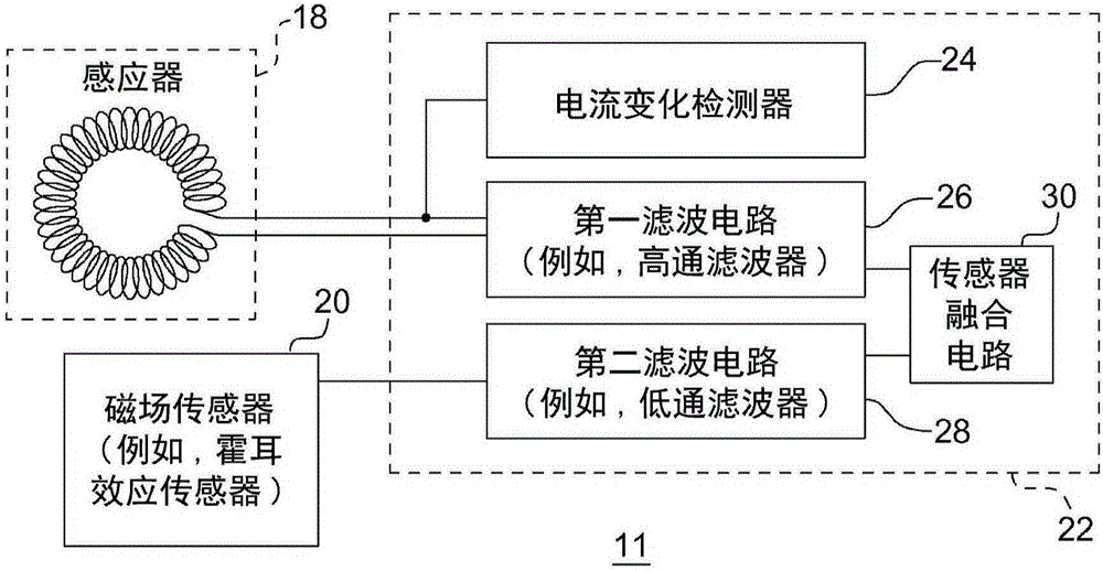
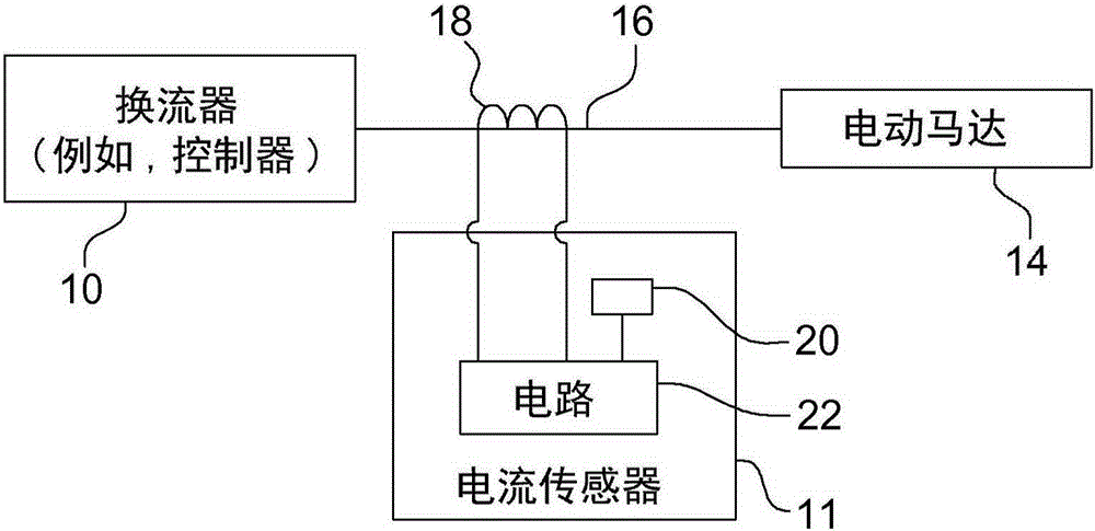
[0019] According to one embodiment, figure 1 A current sensor 11 is shown. As shown, the current sensor 11 includes a sensing conductor 16 (eg, image 3 The sensor 18 for the AC signal component (or the first AC signal component) of the observation signal in 16). Generally, conductors 16 may include conductors 16 located between a source and an electrical load. For example, conductors 16 may include conductors (eg, wires, cables, or busbars) 16 located between an output of inverter 10 or controller and an input of electric motor 14 .

[0020] Alternatively, the conductors 16 may be any power semiconductor device associated with a corresponding one or more output terminals of a corresponding power semiconductor device (eg, an insulated gate bipolar transistor (IGBT) or a metal oxide semiconductor field effect transistor (MOSFET)). conductor, conductive trace, wire, set of wires, bonding wire or set of bonding wires, wherein the current sensor 11 is configured to sense Inver...


PUM


Abstract

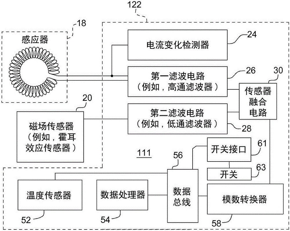
A sensor (11) comprises an inductor (18) for sensing an alternating current signal component of an observed signal. The inductor (18) comprises a substrate, conductive traces associated with different layers of the substrate, and one or more conductive vias for interconnecting the plurality of conductive traces. A magnetic field sensor (20) senses a direct current signal component of the observed signal. A first filtering circuit (26) has a high-pass filter response. The first filtering circuit (26) is coupled to the inductor (18) to provide a filtered alternating current signal component. A second filtering circuit (28) has a low-pass filter response. The second filtering circuit (28) coupled to the magnetic field sensor (20) to provide a filtered direct current signal component. A sensor fusion circuit (30) determines an aggregate sensed current based on the filtered alternating current signal component and the filtered direct current signal component.

Description

technical field [0001] The present disclosure relates to a method and sensor for sensing current in a conductor. Background technique [0002] Vehicles, equipment or machinery may use electric motors controlled by inverters or motor controllers. Prior art sensors can measure the current in one or more input conductors, such as wires or cables, that feed the electric motor from the inverter. More generally, prior art sensors can measure current flow in one or more conductors associated with any power electronics device using a power semiconductor, such as an insulated gate bipolar transistor (IGBT) or a metal oxide semiconductor field Effect Transistor (MOSFET). [0003] Because some prior art sensors used to sense current in conductors associated with electric motors have poor resistance to thermal stress, the prior art sensors may fail prematurely. In some prior art sensors, self-heating of the ferromagnetic core from induced eddy currents and hysteresis losses can contr...

Claims


Application Information

Patent Timeline
Patent Type & Authority Applications(China)
IPC IPC(8): G01R15/20H02P23/00H02P6/16
CPCG01R31/42G01R19/0007G01R15/20G01R15/181
Inventor 波雷吉·N·辛格阿伦·费思科尼尔·D·克莱蒙斯安德鲁·D·维兰德
Owner DEERE & CO
Learn More