An optical signal modulation path, electro-optic modulator and optical transmitter

An electro-optic modulator and optical signal technology, which is applied in the field of optical communication, can solve the problems of adding electrodes, being unfavorable for integration, and having a large number of electrodes.

Active Publication Date: 2018-06-19
HUAWEI TECH CO LTD
View PDF5 Cites 0 Cited by
  • Summary
  • Abstract
  • Description
  • Claims
  • Application Information

AI Technical Summary

Problems solved by technology

[0005] The above-mentioned electro-optic modulator uses the method of changing the length of each electrode to change the size of the phase of the output light after it is transmitted through each electrode. This method only changes the length of the electrode. When the length of each electrode is equal, other parameters are not changed. In the case of changing, if you want to increase the phase of the optical signal accumulated by the electrodes of each optical signal modulation path, you need to increase the number of electrodes, which will lead to a large number of electrodes used by the electro-optic modulator; when the length of each electrode is not equal , and other parameters remain unchanged, if you want to increase the phase of the optical signal that is changed by the electrodes of each optical signal modulation path, you need to increase the length of one or more electrodes, which will cause the electrodes in the electro-optic modulator Consumed electro-optic material increased
The electrodes per unit length in the above electro-optic modulator can change the phase of the optical signal is a constant value, and the phase of the optical signal changed by increasing the electrode accumulation of each optical signal modulation path can be realized by increasing the number of electrodes or changing the length of the electrodes. The size will increase the size of the optical signal modulation channel, thereby increasing the size of the electro-optic modulator, which is not conducive to integration

Method used


Image

  • An optical signal modulation path, electro-optic modulator and optical transmitter
  • An optical signal modulation path, electro-optic modulator and optical transmitter
  • An optical signal modulation path, electro-optic modulator and optical transmitter

Examples


Embodiment 1

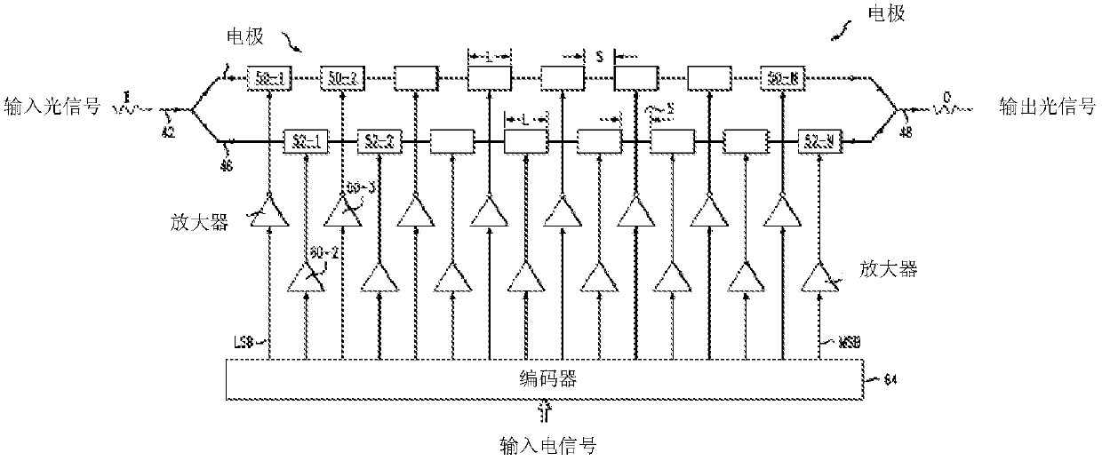
[0060] Figure 4 It is a schematic structural diagram of Embodiment 1 of an optical signal modulation path in the present invention, the optical signal modulation path is applied to an electro-optical modulator, and the optical signal modulation path includes:

[0061] At least two electrodes are sequentially connected from the optical signal input port to the optical signal output port, and each electrode is used to change the phase of the input optical signal when the external input electrical signal is at a high level.

[0062] Such as Figure 4 In the optical signal modulation path shown, the left end is connected to the optical signal input port, and the right end is connected to the optical signal output port. From the optical signal output port of the optical signal modulation path to the optical signal input port, electrode B 0 , Electrode B 1 , Electrode B 2 ,..., electrode B n-1 A total of n electrodes are sequentially connected to form an optical signal modulati...

Embodiment 2

[0081] In the second embodiment, the material parameters of the electro-optic crystals of each electrode on the optical signal modulation path are different, so as to realize the phase change of the optical signal modulation path Subdivision quantification:

[0082] At least two electrodes are connected in sequence, and the material parameters of the electro-optic crystals of each electrode are different, and the ratio of the material parameters of the electro-optic crystals of the electrodes arranged in the order from the optical signal output port to the optical signal input port is: 1:2:2 2 :...:2 n-2 : 2 n-1 , where n is the number of electrodes. Wherein, the material parameter is the product of the cube of the refractive index of the electro-optic crystal of the electrode and the electro-optic coefficient of the electro-optic crystal of the electrode.

[0083] According to formula (1) and formula (2), it can be seen that when the applied electric field is vertical or ...

Embodiment 3

[0099] In the third embodiment, the electric field width of each electrode on the optical signal modulation path is different when the direction of the electric field is perpendicular to the optical signal transmission direction, so as to realize the phase change of the optical signal modulation path Subdivision quantification:

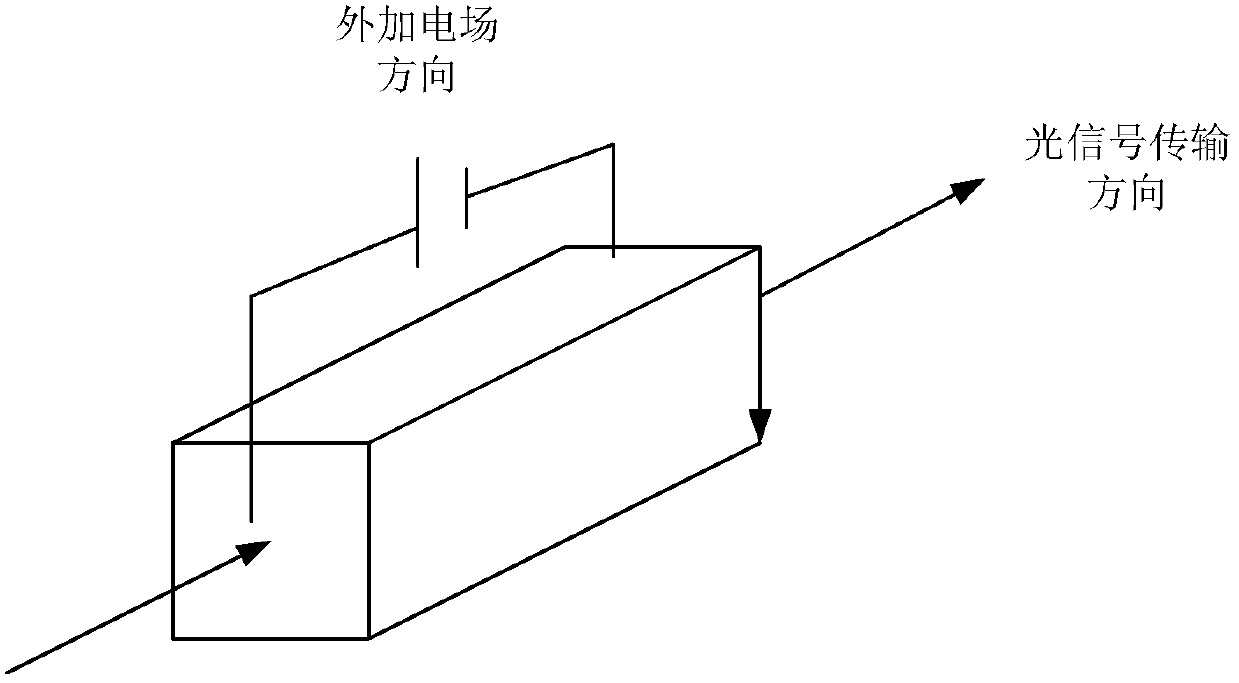
[0100] At least two electrodes are connected in sequence, and the electric field width of each electrode is different. When the electric field action direction is perpendicular to the optical signal transmission direction, the electric field action direction of the electrodes arranged in the order from the optical signal output port to the optical signal input port is lateral. The ratio of the electric field width is: Wherein, n is the number of electrodes.

[0101] According to formula (2), it can be known that when the applied electric field is transverse (the direction of the applied electric field is perpendicular to the direction of optical si...


PUM


Abstract

An optical signal modulation pathway, an electro-optic modulator and an optical transmitter. All electrodes on the optical signal modulation pathway except a reference electrode differ from the reference electrode in the material parameters of electro-optic crystals and / or the width of an electric field when the electric field acts in the transverse direction. The phases of input light signals varied by the other electrodes are greater than the phase of the input light signal varied by the reference electrode. In the case that a particular space is occupied by the entire optical signal modulation pathway, when a high level is accessed to the electrodes on the optical signal modulation pathway, as compared to the situation where only the reference electrode is present on the optical signal modulation pathway, the accumulated value of the phases of the input light signals that can be varied by the entire optical signal modulation pathway can be increased by increasing the phases of the input light signals varied, with no need of the increase in the number of electrodes or the length of individual electrodes.

Description

technical field [0001] The invention relates to the technical field of optical communication, in particular to an optical signal modulation path, an electro-optical modulator and an optical transmitter. Background technique [0002] Electro-optic modulators are mainly based on the basic principle of electro-optic crystals and the linear electro-optic effect in anisotropic polymers, that is, the refractive index of electro-optic crystals changes with the applied external electric field. At present, the more commonly used electro-optical modulators in coherent optical communication systems are LiNbO 3 Mach-Zehnder Modulator (MZM) made of crystal, LiNbO 3 The refractive index of the crystal changes significantly with the voltage of the applied external electric field. Such as figure 1 The structure of the MZM shown in LiNbO 3 The crystal is in the upper and lower two voltage signals V 1 (t) and V 2 Under the action of (t), the refractive index changes, and the optical sig...

Claims


Application Information

Patent Timeline
Patent Type & Authority Patents(China)
IPC IPC(8): G02F1/035
CPCG02F1/035
Inventor 万文通
Owner HUAWEI TECH CO LTD
Why Eureka
Try Eureka