Method and device for compensating for errors of synchronous rotating shafts of numerical control gear shaping machine

A technology of synchronous rotation and compensation method, applied in the direction of gear tooth manufacturing device, gear cutting machine, gear tooth, etc., can solve the problems of different inertia, error, high cost, reduce transmission chain error, improve machining accuracy, and compensate transmission chain error. Effect

Inactive Publication Date: 2016-01-06
HUBEI THREE GORGES POLYTECHNIC
View PDF7 Cites 11 Cited by
  • Summary
  • Abstract
  • Description
  • Claims
  • Application Information

AI Technical Summary

Problems solved by technology

In order to improve the machining accuracy of CNC machine tools, a rotary axis error compensation system is provided in CN202734806U. This system can quickly and accurately measure the rotation angle, thereby improving the accuracy and pass rate of subsequent corrections and improving the efficiency of measurement operations. Only a detection device is provided, and there is no specific error compensation prompt, while CN103817380A provides a method for compensating the error of the synchronous axis of the numerically controlled gear machine tool. The method of adding a virtual axis is used for error compensation, but the method of virtual spindle is used There are certain defects, the data collected by the virtual spindle is not the actual value, and there are still certain errors in the subsequen...

Method used


Image

  • Method and device for compensating for errors of synchronous rotating shafts of numerical control gear shaping machine
  • Method and device for compensating for errors of synchronous rotating shafts of numerical control gear shaping machine

Examples


Embodiment 1

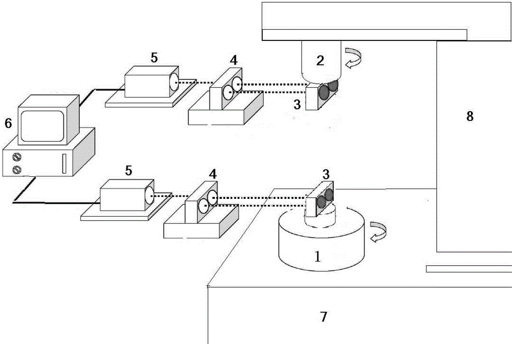
[0036] see figure 1 , using a laser interferometer measurement device used in the error compensation method of the synchronous rotation axis of the CNC gear shaping machine. It includes two sets of laser interferometer measurement systems. 1 The mirror 3 on the rotating spindle C, the workbench 1 is installed on the base 7 of the CNC gear shaping machine, the mirror 3 cooperates with the interference mirror 4, the laser 5 cooperates with the interference mirror 4, and the computer 6 communicates with the Laser 5 is connected.

[0037] Further, the emitting and receiving components of the second group of laser interferometers include a reflector 3 installed on the rotating spindle B of the tool rest 2, and the tool rest 2 is installed on the CNC gear shaping machine body 8, and the reflector 3 and The interference mirror 4 cooperates, the laser 5 cooperates with the interference mirror 4, and the computer 6 is connected with the laser 5 through a signal line.

[0038]Further,...

Embodiment 2

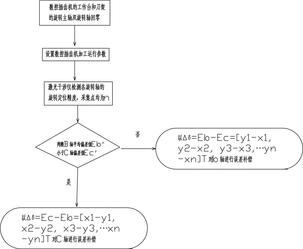
[0040] see figure 2 , a method for compensating an error of a synchronous rotating shaft of a numerically controlled gear shaping machine, comprising the following steps:

[0041] The first step is to install the transmitting and receiving components of the first group of laser interferometers on the rotating spindle of the worktable 1, and install the transmitting and receiving components of the second group of laser interferometers on the rotating spindle of the tool post 2; the two groups of components share A set of control system can perform preliminary measurement and adjustment on the positioning accuracy and repeat positioning accuracy of the rotary axis of the worktable 1 and the tool post 2 separately or simultaneously, so as to ensure that the positioning accuracy and repeat positioning accuracy of the two rotating synchronous axes reach the lowest machining accuracy Requirements above; then use the first group of laser interferometers to measure the positioning ac...


PUM


Abstract

The invention relates to a method for compensating for errors of synchronous rotating shafts of a numerical control gear shaping machine, belongs to the technical field of gear machining and manufacturing, and relates to a high-precision gear digital manufacturing technology, in particular to a method for improving the gear machining accuracy through compensation for errors of synchronous shafts of a gear manufacturing machine tool. A moving workbench and a rotating shaft of a tool rest are measured at the same time through two laser interferometer measuring assemblies, a measuring system obtains movement data of the double synchronous shafts at the same time, and then data processing and error compensation are conducted, so that the machining accuracy of gears is improved.

Description

technical field [0001] The invention belongs to the technical field of gear processing and manufacturing, and relates to digital manufacturing technology of high-precision gears, in particular to a method and a device for improving the processing accuracy of gears by compensating the error of the synchronous shaft of a gear machine tool. Background technique [0002] The key factors that usually affect the machining accuracy of machine tools are: geometric error, thermal error and cutting force error of the machine tool. There are two basic methods to improve the machining accuracy of machine tools: error prevention method and error compensation method. The error prevention method is to eliminate or reduce error sources in the design and manufacturing process, and to meet the machining accuracy requirements by improving the manufacturing accuracy of machine tools. Technology”; the gear shaper after leaving the factory often uses a kind of “soft technology”—error compensation...

Claims


Application Information

Patent Timeline
IPC IPC(8): B23F23/10
Inventor 耿远程于宁波严文超李寒生
Owner HUBEI THREE GORGES POLYTECHNIC
Why Eureka
Try Eureka