Welding technique for crystalline silicon cell of photovoltaic module

A technology of crystalline silicon cells and photovoltaic modules, applied in photovoltaic power generation, welding equipment, circuits, etc., can solve the problems of increased welding difficulty, low welding efficiency, and prone to false welding, etc., to reduce the rate of bad solder joints and improve welding Reliability, the effect of achieving lead-free soldering

Inactive Publication Date: 2016-01-06
刘畅
View PDF4 Cites 5 Cited by
  • Summary
  • Abstract
  • Description
  • Claims
  • Application Information

AI Technical Summary

Problems solved by technology

The existing welding process mainly has the following defects: (1) With the narrowing of the width of the ribbon welded with the cell and the increasing number of ribbons, the distance between the ribbons is getting smaller and smaller, and the existing welding technology will become a bottleneck ; (2) The existing welding technology is to weld the battery sheet and the ribbon together by an electric soldering iron or a string welding machine. The welding is single-piece welding, and then forms a battery string, and the welding efficiency is low; (3) The existing battery The sheet welding process uses tinned copper strips and battery sheets to be welded together using electric soldering iron or a string welding machine under local heat and local force; due to local heat and local force on the battery sheet, the battery sheet is prone to deformation, hidden crack and damage, and will affect the electrical performance of the battery sheet; (4) Using the existing welding process, due to the local stress and local heating of the battery sheet during the welding process, the thickness of the battery sheet should not be too thin; (5) The existing The welding strip used in the welding process needs to be tin-plated on the surface; (6) As the width of the welding strip becomes narrower and narrower, manual welding or string welding machine welding is more difficult, and it is particularly prone to false welding

Method used


Image

  • Welding technique for crystalline silicon cell of photovoltaic module
  • Welding technique for crystalline silicon cell of photovoltaic module
  • Welding technique for crystalline silicon cell of photovoltaic module

Examples


Embodiment 1

[0038] Embodiment 1: a photovoltaic module cell sheet welding process, comprising the following steps:

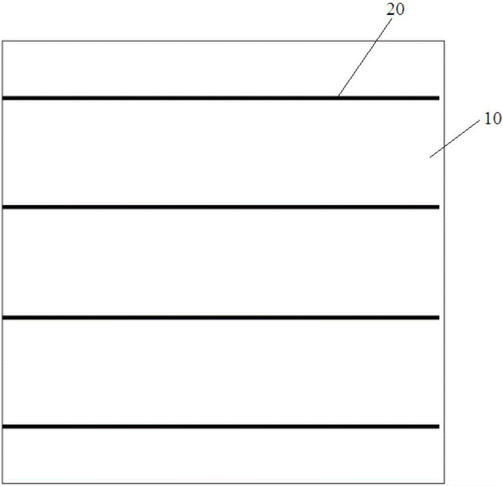
[0039] (1) Solder paste printing: such as figure 1 As shown, solder paste 20 (which may be leaded solder paste or more environmentally friendly lead-free solder paste) is printed on the busbar on the surface of the battery sheet 10 using a solder paste printer; the battery sheet 10 may be a conventional battery sheet, HIT cell or bifacial cell; MWT / IBC back contact cell can also be used, such as Figure 17 As shown, the graphic of the screen printing template is designed according to the main grid graphic and size of the cell;

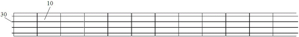
[0040] (2) Ribbon placement: Use a placement machine to accurately place the conductive ribbon 30 (which may be lead-containing ribbon or a more environmentally friendly lead-free ribbon) on the main grid line of the battery sheet 10 On the solder paste 20, a plurality of battery sheets 10 are connected in series through a solder ribbon 30, specif...

Embodiment 2

[0047] Embodiment 2: a photovoltaic module cell sheet welding process, comprising the following steps:

[0048] (1) Solder paste printing: such as figure 1 As shown, the busbars on the surface of the battery sheet 10 are printed with solder paste 20 (which may be leaded solder paste or more environmentally friendly lead-free solder paste) using a solder paste printing machine;

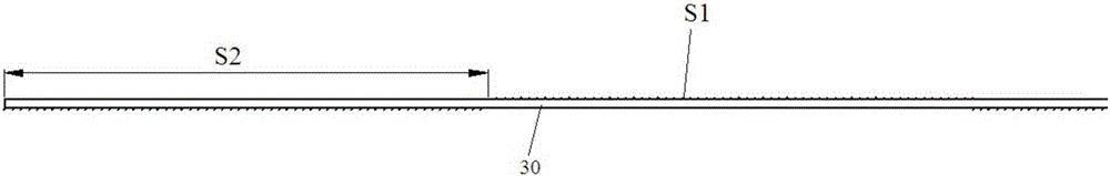
[0049] (2) Ribbon placement: Use a placement machine to accurately place the conductive ribbon 30 (which may be lead-containing ribbon or a more environmentally friendly lead-free ribbon) on the main grid line of the battery sheet 10 On the solder paste 20, a plurality of battery sheets 10 are connected in series through a solder ribbon 30, specifically as image 3 As shown; the solder strip 30 can be tinned solder strip or pure copper strip, and the surface of the pure copper strip does not need to be tinned; as figure 2 As shown, the welding surface S1 and the non-welding surface S2 are circularly...

Embodiment 3

[0055] Embodiment three: a photovoltaic module cell sheet welding process, comprising the following steps:

[0056] (1) Solder paste printing: such as figure 1 As shown, the busbars on the surface of the battery sheet 10 are printed with solder paste 20 (which may be leaded solder paste or more environmentally friendly lead-free solder paste) using a solder paste printing machine;

[0057] (2) Ribbon placement: Use a placement machine to accurately place the conductive ribbon 30 (which may be lead-containing ribbon or a more environmentally friendly lead-free ribbon) on the main grid line of the battery sheet 10 On the solder paste 20, a plurality of battery sheets 10 are connected in series through a solder ribbon 30, specifically as image 3 As shown; the solder strip 30 can be tinned solder strip or pure copper strip, and the surface of the pure copper strip does not need to be tinned; as figure 2 As shown, the welding surface S1 and the non-welding surface S2 are circul...


PUM

PropertyMeasurementUnit
depthaaaaaaaaaa
depthaaaaaaaaaa
heightaaaaaaaaaa

Abstract

The invention relates to a welding technique for a crystalline silicon cell of a photovoltaic module. The welding technique is characterized by comprising the following steps that (1) tin paste which can be lead-contained tin paste and can also be more environment-friendly lead-free tin paste is printed on a main grid line on the surface of the cell; (2) a solder strip which can be a lead-contained solder strip and can also be a more environment-friendly lead-free solder strip is attached to the tin paste on the main grid line of the cell, a welding surface and a non-welding surface are arranged on the front side and/or the back side of the solder strip, and the cell is connected with the welded surface of the welding surface of the solder strip when the solder strip is attached to the cell; and (3) the cell and the solder strip are placed in a reflow soldering furnace together to be integrally heated, the temperature of the front section of the reflow soldering furnace is 130-200 DEG C, the temperature of the rear section of the reflow soldering furnace is 140-230 DEG C, the cell and the solder strip are heated for 1-3 minutes in the front section of the reflow soldering furnace, the cell and the solder strip are heated for 0.5-2 minutes in the rear section of the reflow soldering furnace, and the cell and the strip are cooled to the room temperature at the speed of 2-4 DEG C/s after reflowing, so that tin paste solder is solidified. By the adoption of the welding technique, the welding speed is increased, and the reliability of a welded cell string is high; in addition, lead can be avoided, environmental friendliness is achieved, and cost is low.

Description

technical field [0001] The invention relates to a welding process for crystalline silicon cells of a photovoltaic module, which belongs to the technical field of solar crystalline silicon module production technology. Background technique [0002] In the prior art, the welding technology of crystalline silicon cells of photovoltaic modules generally uses electric soldering iron or stringer to locally heat the cells and ribbons and weld the cells and ribbons together by local force. The existing welding process mainly has the following defects: (1) With the narrowing of the width of the ribbon welded with the cell and the increasing number of ribbons, the distance between the ribbons is getting smaller and smaller, and the existing welding technology will become a bottleneck ; (2) The existing welding technology is to weld the battery sheet and the ribbon together by an electric soldering iron or a string welding machine. The welding is single-piece welding, and then forms a ...

Claims


Application Information

Patent Timeline
Patent Type & Authority Applications(China)
IPC IPC(8): B23K1/008B23K1/20H01L31/18
CPCB23K1/008B23K1/20H01L31/1804H01L31/188Y02E10/547Y02P70/50
Inventor 刘畅
Owner 刘畅
Why Eureka
Try Eureka