Waste heat recovery device and process for dusty flue gas

A waste heat recovery device and waste heat recovery technology, applied in the direction of reducing greenhouse gases, climate sustainability, lighting and heating equipment, etc. Effect

Inactive Publication Date: 2016-01-06
INST OF PROCESS ENG CHINESE ACAD OF SCI
View PDF7 Cites 3 Cited by
  • Summary
  • Abstract
  • Description
  • Claims
  • Application Information

AI Technical Summary

Problems solved by technology

[0004] The above waste heat recovery devices are all developed for the needs of different industries. However, when these devices recover waste heat from dusty flue gas, problems such as blockage of the air outlet will occur. Therefore, they cannot be used for dusty flue gas.

Method used


Image

  • Waste heat recovery device and process for dusty flue gas

Examples


Embodiment 1

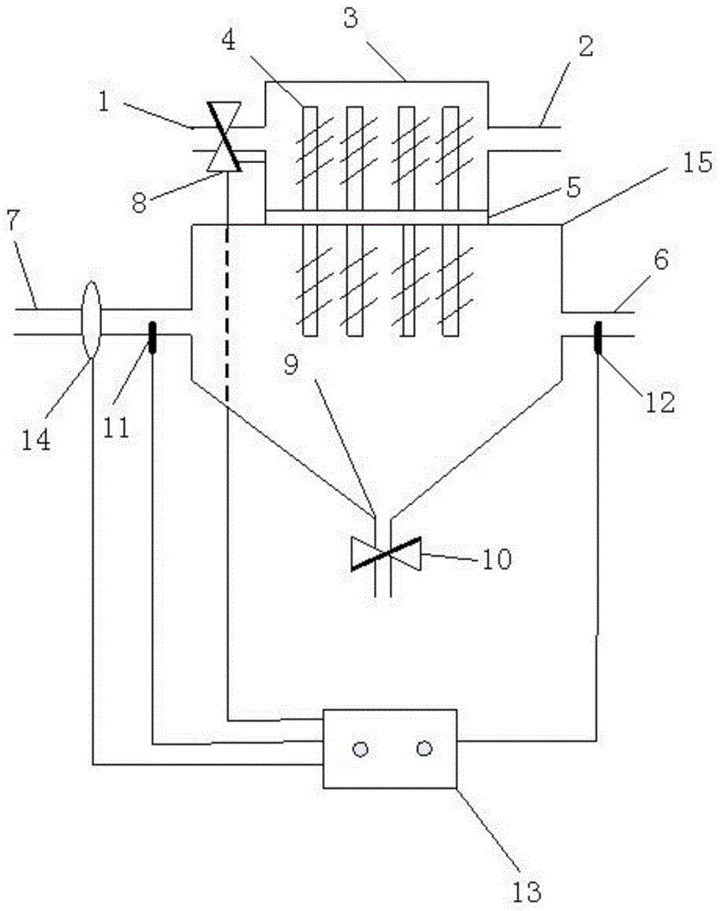
[0050] A waste heat recovery device for dusty flue gas such as figure 1 As shown, it includes a shell, a heat pipe 4 and a heat shield 5 . The housing is divided into upper and lower parts by the heat insulation board 5, which are respectively the upper housing 3 and the lower housing 15. The two sides of the upper housing 3 are respectively provided with a cold water inlet 1 and a hot water outlet 2, and the two sides of the lower housing 15 are respectively A flue gas inlet 7 and a flue gas outlet 6 are provided. The bottom of the lower shell 15 is provided with a smoke and dust outlet 9, and a valve 10 is installed at the smoke and dust outlet 9. The upper shell 3 is square, and the lower shell 15 is a cone with a cone angle of 60°. Conical shape; a heat pipe 4 is installed on the heat shield 5, one end of the heat pipe 4 is located in the upper housing 3, and the other end of the heat pipe 4 is located in the lower housing 15; the cold water inlet 1 is equipped with an ele...

Embodiment 2

[0053] Utilize the device described in embodiment 1 to carry out waste heat recovery of dusty flue gas:

[0054] Set the flow rate to 50000m 3 / h, the dust-containing flue gas with a temperature of 300°C enters the lower housing 15 through the flue gas inlet 7, the number of heat pipes is 32, and the length of the heat pipes in the lower housing is 2 / 3 of the total length of the heat pipes. The gas exchanges heat with the heat pipe 4 in the lower shell, and is discharged through the flue gas outlet 6. At this time, the temperature of the flue gas can drop to 150°C, and the smoke and dust settle in the lower shell 15. The waste heat recovery device works for half a month and opens the valve 10 to clean the dust. , to avoid dust deposition blocking the flue gas outlet 6. The waste heat recovery efficiency at this time was 95%.


PUM


Abstract

The invention provides a waste heat recovery device and process for dusty flue gas. The waste heat recovery device comprises a shell, a heat pipe and a thermal insulation plate; the thermal insulation plate divides the shell into an upper portion and a lower portion which are an upper shell and a lower shell respectively; a heat exchange medium inlet and a heat exchange medium outlet are formed in the upper shell; the lower shell is conical and provided with a flue gas inlet and a flue gas outlet, and a flue dust outlet is formed in the bottom of the lower shell; the heat pipe is installed on the thermal insulation plate, one end of the heat pipe is located inside the upper shell, and the other end of the heat pipe is located inside the lower shell. By means of the waste heat recovery device for the dusty flue gas, the waste heat recovery efficiency for the dusty flue gas is high; device blockage is avoided in the waste heat recovery process; besides, the waste heat recovery device is simple in structure and intelligent, the waste heat recovery process for the dusty flue gas is short, flue gas temperature can be effectively reduced, and smooth operation of the subsequent processes of flue gas treatment can be guaranteed.

Description

technical field [0001] The invention belongs to the technical field of waste heat recovery of flue gas, and in particular relates to a waste heat recovery device and process for dusty flue gas. Background technique [0002] In the process of flue gas dust removal, some dust collectors are easily damaged at higher flue gas temperatures, such as bag filter, and the filter material and filter bag will be damaged at higher temperatures, thus affecting the dust removal effect. Therefore, it is necessary to cool down the dust-laden flue gas before dust removal, and the waste heat recovery device is the preferred cooling device for cooling and recovering heat energy. [0003] At present, there are many studies on waste heat recovery devices. For example, CN201020108217.1 provides a waste heat recovery device for textile printing and dyeing waste gas, including a shell and gravity heat pipes; several gravity heat pipes are arranged in several rows in the shell. , the inner cavity o...

Claims


Application Information

Patent Timeline
Patent Type & Authority Applications(China)
IPC IPC(8): F23J15/06
CPCY02E20/30
Inventor 朱廷钰徐文青周璇
Owner INST OF PROCESS ENG CHINESE ACAD OF SCI
Why Eureka
Try Eureka