Laser beam wavefront correction system and method

A wavefront correction and laser beam technology, applied in the field of laser beam wavefront correction systems, can solve problems such as damage to optical components, high power density, and difficulty in calibration, and achieve the effects of small footprint, simple optical system, and cost reduction.

Inactive Publication Date: 2016-01-06
LASER FUSION RES CENT CHINA ACAD OF ENG PHYSICS
View PDF6 Cites 19 Cited by
  • Summary
  • Abstract
  • Description
  • Claims
  • Application Information

AI Technical Summary

Problems solved by technology

This method has certain problems in the application of laser systems with small F-number focusing (such as ultrashort pulse laser devices), such as space limitations, complicated debugging and difficult calibration, etc.
In addition, due to the small beam aperture at the target point, when performing dynamic wavefront measurement, due to the high power density, it is very easy to damage the optical components
[0004] Therefore, the traditional wavefront correction technology cannot control the wavefront distortion at the target point more accurately and conveniently.

Method used


Image

  • Laser beam wavefront correction system and method
  • Laser beam wavefront correction system and method
  • Laser beam wavefront correction system and method

Examples


Embodiment Construction

[0030] The technical solutions in the embodiments of the present invention will be clearly and completely described below in conjunction with the embodiments of the present invention. Apparently, the described embodiments are only some of the embodiments of the present invention, not all of them. Based on the embodiments of the present invention, all other embodiments obtained by persons of ordinary skill in the art without making creative efforts belong to the protection scope of the present invention.

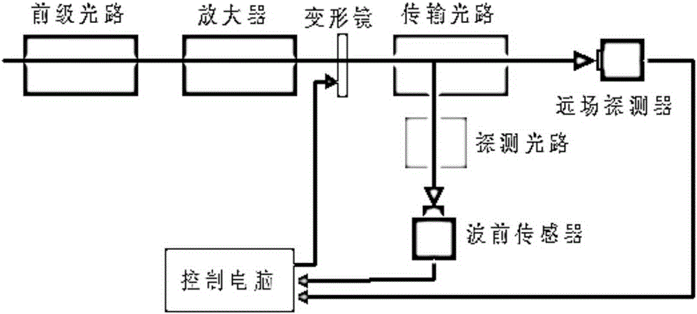
[0031] refer to figure 1 , a laser beam wavefront correction system, which includes a main laser light path, a deformable mirror and a high-voltage drive, a far-field detector (generally a CCD), a wavefront sensor, a detection light path, and a control computer. The main laser light path includes a front-stage Optical path and transmission optical path, the deformable mirror is arranged between the front-stage optical path and the transmission optical path, and is connected w...


PUM


Abstract

The invention provides a laser beam wavefront correction system, comprising a main laser path, a deformable mirror and a high-voltage driver, a far-field detector, a wavefront sensor, a detection light path and a control computer. A far-field sensor and the wavefront sensor can precisely realize wavefront correction of a whole light beam only by utilizing main laser of a laser system. The laser beam wavefront correction method provided by the invention uses a far-field information feedback algorithm to perform closed-loop control on static wavefront distortion, through a reference transition transfer technology, transits a static wavefront to the wavefront sensor, then performs dynamic emission, collects dynamic waveform, and finally controls the deformable mirror to realize wavefront correction of a whole system. The method is advantaged by being capable of effectively avoiding the problem of wavefront detection and calibration in a small-F-number focusing system, lowering a requirement for system debugging precision, not needing to add an extra calibration light source, and being capable of precisely realizing effective control of to-target wavefront distortion of the whole system.

Description

technical field [0001] The invention belongs to the technical field of laser system beam quality control, and in particular relates to a laser beam wavefront correction system and method. Background technique [0002] In laser systems, especially high-power solid-state laser systems, in order to pursue higher beam quality, it is usually necessary to control wavefront distortion. The traditional wavefront correction system includes a set of deformable mirrors and high-voltage drivers, a set of wavefront sensors, and a set of control software. In order to realize the aberration calibration of the detection optical path, a single-mode fiber laser is generally required as a calibration light source. The wavefront sensor is often located in the beam diagnostic package. The matching between the beam aperture and energy and the Hartmann sensor is realized by rationally designing the diagnostic optical path. The position of the Hartmann and the position of the single-mode fiber cali...

Claims


Application Information

Patent Timeline
Patent Type & Authority Applications(China)
IPC IPC(8): G02B26/06
CPCG02B26/06
Inventor 王德恩代万俊胡东霞周维张鑫张晓璐杨英周凯南薛峤袁强赵军普孙立粟敬钦朱启华
Owner LASER FUSION RES CENT CHINA ACAD OF ENG PHYSICS
Why Eureka
Try Eureka