
Novel shielding cable

A shielded cable, a new type of technology, applied in the direction of insulated cables, communication cables, cables, etc., can solve the problems of slowing down the production and processing speed, signal attenuation, and production efficiency, so as to solve the resonance problem, solve the attenuation and production The effect of speed reduction

Inactive Publication Date: 2016-01-06
通盈电业(深圳)有限公司
View PDF6 Cites 2 Cited by
  • Summary
  • Abstract
  • Description
  • Claims
  • Application Information

AI Technical Summary

Problems solved by technology

[0005] Although this technology can solve the problem of attenuation and sudden drop in the signal transmission process, there are some problems in the process of partially folding the metal-coated resin tape back
First of all, the part to be folded back accounts for less than half of the entire bandwidth, and the width is very small. It is difficult to ensure that the folded back width is consistent during the folding operation of large machines, and the width may vary. If the folded width is too small , the conductivity of the metal foil in the overlapping portion will be insufficient, and if the foldback width is too large, an additional metal-clad resin tape will be required to be wound and easily disturbed; secondly, compared with the previous technology, the foldback process has High difficulty, easy to jam and break the tape during the winding process of the metal-clad resin tape; finally, due to the increase of the folding process, the speed of the entire production process will be slowed down and the production efficiency will be reduced

Method used


Image

  • Novel shielding cable
  • Novel shielding cable
  • Novel shielding cable

Examples


Embodiment Construction

[0024] In the description of the present invention, it should be understood that the orientation or positional relationship indicated by the terms "center", "upper", "lower", "front", "rear", "left", "right" etc. are based on The orientation or positional relationship shown in the drawings is only for the convenience of describing the present invention and simplifying the description, and does not indicate or imply that the referred device or element must have a specific orientation, be constructed and operated in a specific orientation, and therefore cannot be understood as Limitations on the Invention. In addition, the terms "first" and "second" are used for descriptive purposes only, and should not be understood as indicating or implying relative importance.

[0025] In the description of the present invention, it should be noted that unless otherwise specified and limited, the terms "installation", "connection" and "connection" should be understood in a broad sense, for ex...


PUM

PropertyMeasurementUnit
thicknessaaaaaaaaaa
thicknessaaaaaaaaaa
Overlap degreeaaaaaaaaaa

Abstract

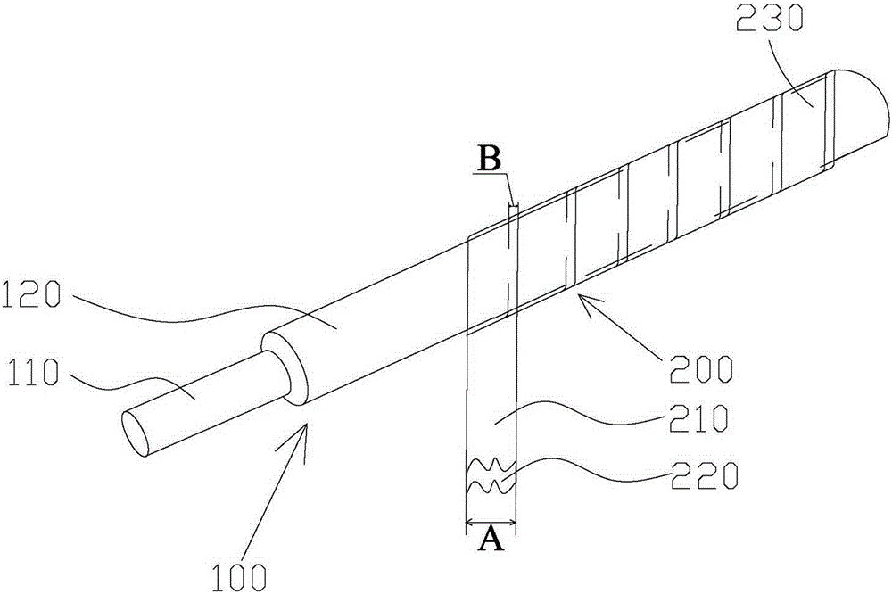
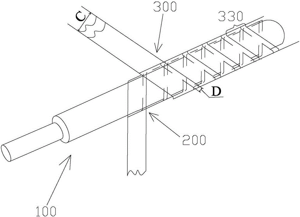
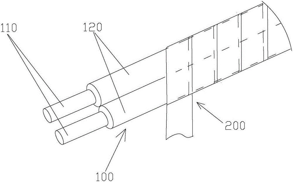
Provided is a novel shielding cable comprising at least one signal line and two metallic conductive shielding tapes covering the periphery of the signal line. The metallic conductive shielding tape is formed by a metallic foil covering a side of a plasticity base material. The metallic foil of the first metallic conductive shielding tape faces outwardly, is spirally wound around the signal line, and defines a plurality of first spiral coils. The metallic foil of the second metallic conductive shielding tape faces inwardly, reversely spirally wound around the first metallic conductive shielding tape, and defines a plurality of second spiral coils. Continuous electrical contact is formed between the first metallic conductive shielding tape and the second metallic conductive shielding tape. The two metallic conductive shielding tapes are wound in a crossed manner such that the metallic foils of the two metallic conductive shielding tapes can be completely and tightly combined and cannot generate periodic breakpoints, thereby guaranteeing continuity of a conductive surface. Thus, a resonance problem generated by periodic fluctuation of shielding conductive surface capacitance is solved and an effect of solving a high-frequency point abrupt attenuation.

Description

technical field [0001] The invention relates to a shielded cable, in particular to a novel shielded cable covered with a metal conductive shielding tape on the periphery of a signal line. Background technique [0002] For the shielded cable of the signal line, during the signal transmission process, due to the overlapping height difference caused by the metal tape wrapping, the capacitance fluctuates periodically, which will cause the signal to resonate during the transmission process, resulting in a sudden attenuation of the signal at high frequencies. drop problems, ultimately affecting signal integrity. [0003] At present, shielded cables on the market are taped by wrapping a single core wire or two core wires with metal foil, and the overlapping rate is generally more than 25%. The outside is covered with a layer of mylar to play a fixed role. The shielded cable is shielded with metal. Due to the overlapping height difference when the metal tape is wrapped, the capaci...

Claims


Application Information

Patent Timeline
Patent Type & Authority Applications(China)
IPC IPC(8): H01B7/17H01B11/00
Inventor 陈明贤于建军
Owner 通盈电业(深圳)有限公司
Learn More