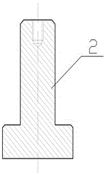
A rotary table for free forging

A technology for rotating worktables and worktables, applied in the direction of manufacturing tools, driving devices of forging presses, power hammers, etc., can solve the problems of hidden dangers of worktable safety, low work efficiency, bumped workpieces, etc., so as to reduce labor intensity and save money. Labor cost and the effect of improving work efficiency

Active Publication Date: 2017-05-17
JIANGSU LIANFENG ENERGY EQUIP
View PDF6 Cites 0 Cited by
  • Summary
  • Abstract
  • Description
  • Claims
  • Application Information

AI Technical Summary

Problems solved by technology

In this mode, it takes at least 2 minutes for each position of the workpiece to be changed, and the operator who operates the machine must stay close to the high-temperature workpiece during these 2 minutes, and must concentrate on the operation, otherwise the workpiece will fail due to no tightening or turning over. If it falls to the ground and hurts the workpiece, it will cause the workpiece to be scrapped or need to be reheated in the heating furnace. The existing workbench not only has certain safety hazards, but also has low work efficiency. Therefore, a new technical solution is urgently needed to solve the above technical problems. question

Method used


Image

  • A rotary table for free forging
  • A rotary table for free forging
  • A rotary table for free forging

Examples


Embodiment 1

[0041] Embodiment 1: see Figure 1-Figure 13, a rotary table for free forging, the rotary table includes a motor, a reducer, a coupling arranged between the motor and the reducer, the table also includes a lower pier connecting seat 1, a rotary table Spring seat 2, rotating table spring 3, rotating table circular slideway 4, rotating table steel ball 5, rotating table lower upsetting backing plate 6, rotating table’s lower upsetting seat 7, rotating table’s lower pier mandrel 8 , Upsetting mandrel bushing 9 under the rotating workbench, the large ring gear 10 of the rotating worktable, the pinion 11 of the rotating workbench, the brake device 12 of the rotating workbench, wherein the pinion 11 is connected with the reducer through a shaft, and the pinion 11 of the The other end is connected with the large ring gear 10, the large ring gear 10 is set on the outer ring of the lower pier backing plate 6 and welded with the lower pier backing plate 6, the lower abutment 7 is arrang...

Embodiment 2

[0042] Example 2: see Figure 1-Figure 13 , as an improvement of the present invention, the workbench also includes an annular slideway 4 and a steel ball 5, the annular slideway 4 is supported on the spring of the lower upsetting seat connection seat, and the steel ball supports the lower upsetting seat backing plate above, The annular slideway 4 is provided with a groove ring 5, the steel ball 5 is placed in the groove ring on the annular slideway, and the inner ring groove is arranged on the connecting seat, and the inner ring groove of the connecting seat positions the annular slideway 4 . When the table rotates, the steel balls produce rolling friction with the lower upsetting backing plate. The technical scheme is equipped with annular slideways and steel balls, which can effectively prevent the excessive rotation torque of the workbench or the phenomenon of burning the motor and reducer during the forging process of the forging. The rest of the structures and advantag...

Embodiment 3

[0043] Embodiment 3: see Figure 1-Figure 13 , as an improvement of the present invention, the workbench further includes a spring 3 , and the spring 3 is arranged on the spring seat 2 . It can ensure that the lower pier is in a suspended state when the worktable rotates to reduce the rotational torque, and can ensure that the force of the forging press hammer can be transmitted to the forging press base when the forging press hammer is pressed down, preventing the base from tipping and ensuring that the pressure surface of the forging is flat. The rest of the structures and advantages are exactly the same as in Embodiment 1.


PUM


Abstract

The invention relates to a rotary worktable for free forging. The rotary worktable for free forging is characterized by comprising a motor, a speed reducer, a coupler arranged between the motor and the speed reducer, a lower pier base connecting seat, a spring seat, a lower pier base plate, a lower pier base, a large gear ring and a pinion. The pinion is connected with the speed reducer through a belt, and the other end of the pinion is connected with the large gear ring. The outer circle of the lower pier base plate is sleeved with the large gear ring, and the large gear ring is welded to the lower pier base plate. The lower pier base is arranged on the lower pier base plate. The spring seat is arranged on the lower pier base connecting seat. By means of the technical scheme, the operation time of an operation machine is shortened, the time that operators make contact with high-temperature steel billets is shortened, the risks of burning injury are avoided for the operators, the number of the operators is reduced, and the production efficiency is improved.

Description

technical field [0001] The invention relates to a workbench, in particular to a rotary workbench for free forging, which belongs to the technical field of forging equipment. Background technique [0002] The free forging hydraulic press generally uses a clamp-type manipulator to clamp the forging to flip and move. It is inconvenient to move and rotate the forging. The clamp-type manipulator should clamp the workpiece on the ordinary workbench, turn it over or move it, and then put it into the ordinary work. on the stage, and let go. In this mode, it takes at least 2 minutes for each position of the workpiece to be changed, and the operator who operates the machine must stay close to the high-temperature workpiece during these 2 minutes, and must concentrate on the operation, otherwise the workpiece will fail due to no tightening or turning over. If it falls to the ground and hurts the workpiece, it will cause the workpiece to be scrapped or need to be reheated in the heatin...

Claims


Application Information

Patent Timeline
Patent Type & Authority Patents(China)
IPC IPC(8): B21J13/00B21J9/12B21J9/20B21J9/06B21J7/28
Inventor 伍魁伟杭建平伍淑林张良斌
Owner JIANGSU LIANFENG ENERGY EQUIP
Why Eureka
Try Eureka