
Buffer amplifier circuit

A buffer amplifier, amplifier circuit technology, applied in the layout of amplifier protection circuit, amplifier, charge amplifier, etc., can solve the problem of unsuitable voltage amplifier and so on

Active Publication Date: 2016-01-13
李海升
View PDF6 Cites 0 Cited by
  • Summary
  • Abstract
  • Description
  • Claims
  • Application Information

AI Technical Summary

Problems solved by technology

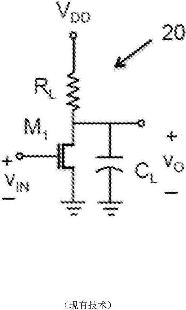
However, the last type provides a voltage gain close to unity or slightly less, and as a result, it has been suitable only as a buffer amplifier, not as a voltage amplifier

Method used


Image

  • Buffer amplifier circuit
  • Buffer amplifier circuit
  • Buffer amplifier circuit

Examples


Embodiment Construction

[0050] The following description provides a discussion of various concepts related to and embodiments of the inventive apparatus and methods with respect to signal amplification circuits and those embodiments. It should be appreciated that the various concepts introduced above and discussed in greater detail below can be implemented in any of numerous ways, as the disclosed concepts are not limited to any particular manner of implementation. Examples of specific implementations and applications are provided primarily for purposes of illustration.

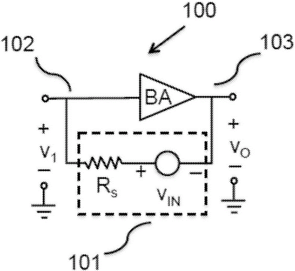
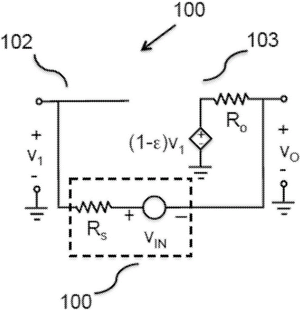
[0051] Aspects of the invention provide a discrete-time amplifier topology based on a buffer amplifier (hereinafter "buffer"). A buffer is an amplifier that provides a voltage gain substantially close to unity, while providing high input resistance and low output resistance, as will be understood by those skilled in the art. Those skilled in the art will also understand that a source-follower circuit or an emitter-follower circuit ...


PUM


Abstract

Amplifier circuits implemented with a buffer amplifier with a voltage gain substantially equal to one. In one example, a continuous-time amplifier is implemented by applying the input source across the input and the output terminals of the buffer amplifier. In another example, a discrete-time amplifier is implemented. During the sampling phase at least one input voltage is sampled, and during the transfer phase at least one capacitor is coupled across the input and the output terminals of a buffer amplifier to effectuate an amplification.

Description

technical field [0001] This application relates to microelectronic circuits and circuit design and operation. More specifically, the present application relates to microelectronic amplifier circuits used in semiconductor devices, integrated circuits, and other electronic devices. [0002] related application [0003] This application is related to, and claims priority to, U.S. Provisional Application No. 61 / 791,911, entitled "Buffer-Based Signal Amplification," filed March 15, 2013, which is hereby incorporated by reference and enter. Background technique [0004] Signal amplification is widely used in various electronic systems. For example, in a wireless communication system, a low-noise amplifier (LNA) in a receiver amplifies tiny signals picked up by an antenna. The amplified signal is then filtered, demodulated and further amplified again. This signal is usually converted to a digital signal by an analog-to-digital converter. An analog-to-digital converter typica...

Claims


Application Information

Patent Timeline
IPC IPC(8): H03G3/30H03F1/52H03F1/56
CPCH03F3/62H03F3/70H03F2200/156H03F2200/159H03F2200/357H03F2200/42H03M1/468H03F3/16H03H19/004H03M1/1245G11C27/024H03F3/005
Inventor 李海升
Owner 李海升
Learn More