

Traditional Chinese medicine pulse manifestation acquisition apparatus, noise reduction system and noise reduction method
A collection device and pulse condition technology, which is applied in the field of medical instruments, can solve the problems that the sensor is susceptible to external interference, and the repeatability and accuracy of the traditional Chinese medicine pulse conditioner are low, so as to achieve the effect of improving the repeatability and accuracy
- Summary
- Abstract
- Description
- Claims
- Application Information
AI Technical Summary
Problems solved by technology
Method used
Image

Examples
Embodiment 1
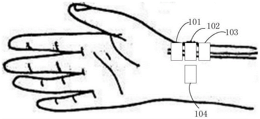
[0046] The TCM pulse acquisition device includes a pressure sensor array and an internal circuit. The location of the pressure sensor is as figure 1 shown. Among them, the pressure sensor array element 101, the pressure sensor array element 102 and the pressure sensor array element 103 are respectively arranged corresponding to the "inch", "off" and "ruler" pulse points at the wrist of the human body, and are used to collect the pulse points of "inch", "off" and "ruler" at the wrist of the human body. This type of sensor can be called a pulse sensor; the pressure sensor array element 104 can be placed near the pulse sensor on the wrist, but it will not be pressed on the position of the arterial blood vessel, for collecting Incoming vibration noise, this type of sensor can be called a noise sensor. In order to avoid errors caused by each pulse sensor array element not accurately corresponding to the pulse points of "inch", "off" and "foot" when the traditional Chinese medicin...
Embodiment 2
[0077] The above-mentioned embodiment 1 is an example in which three pressure sensor elements or arrays are used as pulse sensors, and one pressure sensor element is used as a noise sensor. Considering that the physiological structure of the human body is different, each person's blood vessel position and curvature are different, and for the convenience of people without any medical knowledge can use this product, the pressure sensor array elements that make up the pressure sensor array 401 in Embodiment 2 are placed on the wrist The position of the position is not set in advance, that is, the positional relationship between each pressure sensor and the pulse point and the arterial blood vessel is not limited, but the signal collected by the pressure sensor is used to judge whether it belongs to the pulse sensor or the noise sensor; the pressure sensor can be arranged as Figure 6 The rectangular structure shown can also adopt other structures, as long as it is ensured that som...
Embodiment 3
[0080] The implementation of judging the sensor type (whether the pulse is collected or the noise collected) in Embodiments 1 and 2 will be described below. Figure 7 A flow chart of the steps of the first judgment method is shown. The flow of this step is described as follows:
[0081] First, frequency domain conversion is performed on all sensor data;
[0082] Secondly, perform spectral analysis on the converted data to find the corresponding frequency with the strongest spectral line;
[0083] Afterwards, according to the characteristics of the pulse spectrum, the pulse sensor and the noise sensor are distinguished. The frequency can be compared with the normal pulse range of the human body (normal heartbeat 45-120 beats per minute). If it falls within this range, it is considered normal, otherwise it is considered that there is no pulse signal in the frequency spectrum.
[0084] Figure 8 A flow chart of the steps of the second judging manner is shown. The basic princ...
PUM
 Abstract
Description
Claims
Application Information