
Bi-metal metallurgy composite pipe welding method

A welding method and bi-metal technology, applied in welding equipment, metal processing, metal processing equipment, etc., can solve the problems of plastic toughness decline, hindering the welding forming of bi-metal composite pipes, joint mechanical properties and corrosion resistance, etc. The effect of efficient automated production

Inactive Publication Date: 2016-01-20
XI AN JIAOTONG UNIV
View PDF3 Cites 10 Cited by
  • Summary
  • Abstract
  • Description
  • Claims
  • Application Information

AI Technical Summary

Problems solved by technology

For example, during the welding process, the formation of the solidification transition layer of the joint can easily lead to the formation of brittle phases in the weld metal, which reduces the plasticity and toughness of the joint; the migration of alloy element carbon at the joint interface reduces the mechanical properties and corrosion resistance of the joint, etc. Problems hindering the welding and forming of bimetal composite pipes

Method used


Image

  • Bi-metal metallurgy composite pipe welding method
  • Bi-metal metallurgy composite pipe welding method
  • Bi-metal metallurgy composite pipe welding method

Examples


Embodiment Construction

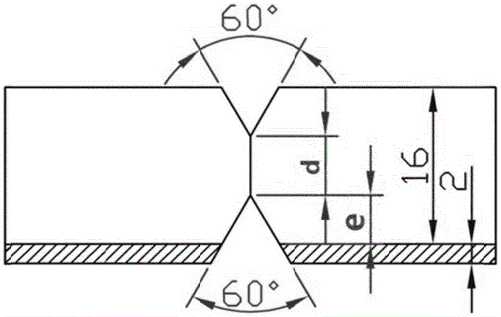
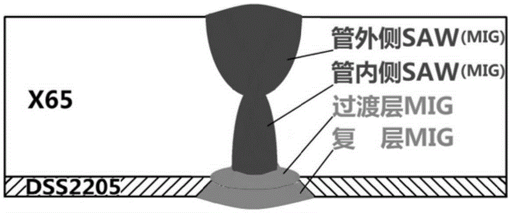
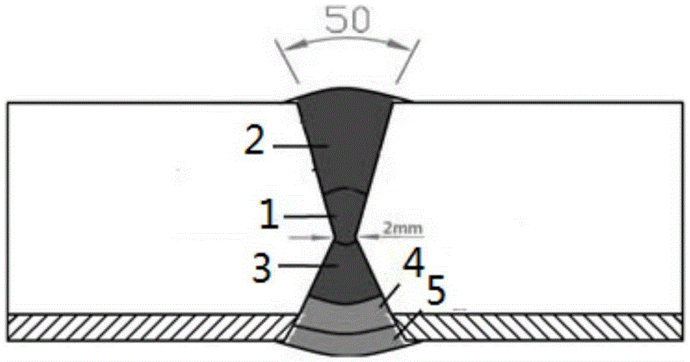
[0028] A method for welding bimetallic metallurgical composite pipes of the present invention comprises the following steps:

[0029] 1) The DSS2205-X65 bimetallic composite board is connected in a docking manner, and the X-shaped groove is removed;

[0030] 2) Use MAG to perform welding at the center of the X-shaped groove from the outside to form the first outer base weld 1;

[0031] 3) MAG is used to weld the first outer base layer weld 1 from the outside to form the second outer base layer weld 2;

[0032] 4) Use MAG to weld at the center of the X-shaped groove from the inside to form the inner base weld 3;

[0033] 5) MAG is used to perform welding on the inner base layer weld seam 3 from the inside to form a transition layer weld seam 4;

[0034] 6) MAG is used to weld the transition layer weld seam 4 from the inside to form a multilayer weld seam 5; complete the welding of the entire composite pipe.

[0035] see figure 1 As shown, in this embodiment, the automatic l...


PUM

PropertyMeasurementUnit
Thicknessaaaaaaaaaa
Thicknessaaaaaaaaaa

Abstract

The invention discloses a bi-metal metallurgy composite pipe welding method. The bi-metal metallurgy composite pipe welding method includes the steps that (1) an X-type groove is formed in an SS2205-X65 bi-metal composite plate in a butt-joint mode; (2) metal active gas (MAG) is used for carrying out welding on the center of the X-type groove from the outer side, and a first outer side base layer welding joint is formed; (3) the MAG is used for carrying out welding on the first outer side base layer welding joint from the outer side, and a second outer side base layer welding joint is formed; (4) the MAG is used for carrying out welding on the center of the X-type groove from the inner side, and an inner side base layer welding joint is formed; (5) the MAG is used for carrying out welding on the inner side base layer welding joint from the inner side, and a transition layer welding joint is formed; and (6) the MAG used for carrying out welding on the transition layer welding joint from the inner side, and a composited layer welding joint is formed. Through reasonable section of the welding method, welding materials and the welding process, the chemical components and structure of the welding joints are controlled, and welding on a composited layer, a transition layer and a base layer are carried out respectively, so that efficient and automatic production of SS2205-X65 bi-metal composite pipes is realized.

Description

【Technical field】 [0001] The invention relates to the field of welding technology, in particular to a method for welding bimetallic metallurgical composite pipes. 【Background technique】 [0002] Domestic research on composite pipes is mainly focused on small-diameter composite pipes, and the main means are diameter expansion and explosive compounding. There are certain defects in the pipe performance and service life of the composite pipe through diameter expansion, explosive composite and other means. It is a flexible, efficient and low-cost method to manufacture layered bimetallic composite pipes by using metallurgically bonded layered composite plates as raw materials and welding after cold forming. It first heat-combines two slabs of different materials with a super-high-power hot rolling mill, then rolls them into tube blanks with UO or JCO technology, and then welds them longitudinally. Compared with the expanded diameter composite pipe and the explosive composite pi...

Claims


Application Information

Patent Timeline
IPC IPC(8): B23K9/167B23K9/235B23K103/02B23K101/06
CPCB23K9/167B23K9/235B23K2101/06B23K2103/04
Inventor 张建勋李振岗王剑龙苟宁年李瑞娟
Owner XI AN JIAOTONG UNIV
Learn More