Air volume adjusting valve with novel structure

An air volume control valve, a new structure technology, applied in the valve shell structure, lift valve, valve details and other directions, can solve the problems of complex structure, bulky, complex assembly structure, etc., to reduce manufacturing costs and maintenance costs, realize automation, achieve the effect of integration

Active Publication Date: 2016-01-20
广东科艺普实验室设备研制有限公司
View PDF12 Cites 17 Cited by
  • Summary
  • Abstract
  • Description
  • Claims
  • Application Information

AI Technical Summary

Problems solved by technology

[0007] The first defect is that since Venturi valves and butterfly valves are generally manufactured by two different companies, they each have their own controllers, even if their control systems are automatically linked and controlled due to control signal distortion, errors, etc. , but the overall control accuracy is not high, and the precise matching of air volume and air pressure control cannot be realized; the second defect is that the Venturi valve itself not only has a valve cavity for installing the float but also has a control valve cavity for controlling the axial position of the float, and also There are also mechanical and electrical controllers, so that the Venturi valve itself is bulky and complex in structure, and because the Venturi valve and the butterfly valve are two independent control valves, not only the purchase and assembly costs are high, but also the assembly structure is relatively complicated

Method used


Image

  • Air volume adjusting valve with novel structure
  • Air volume adjusting valve with novel structure
  • Air volume adjusting valve with novel structure

Examples


Embodiment Construction

[0041] The structure of the air volume regulating valve with a new structure applying the technical solution of the present invention will be further described below in conjunction with the accompanying drawings.

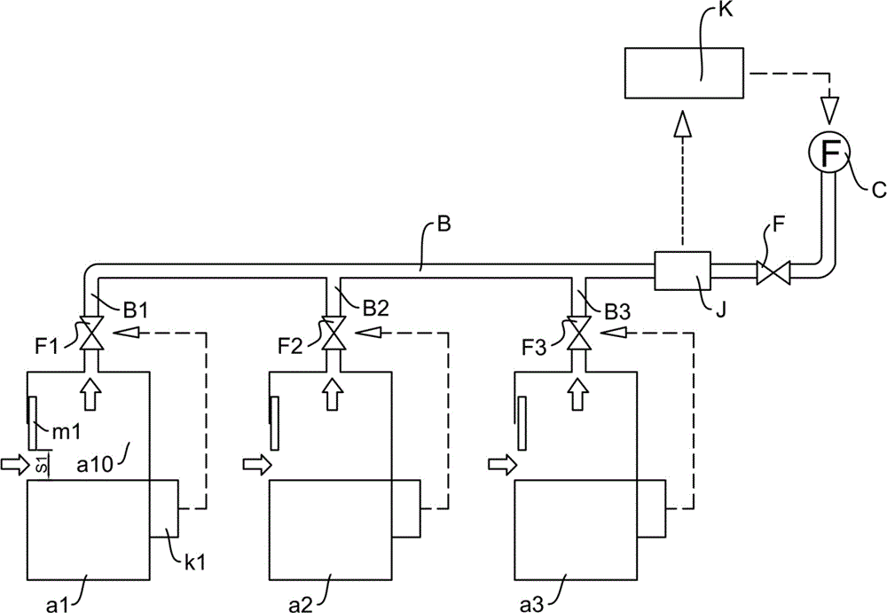
[0042] Such as figure 1 As shown, the schematic diagram of the layout structure of the ventilation system applied in the laboratory, as the description given above, in the process of using the fume hood a1, when there are self-interference factors or external interference factors, the air volume is required The regulating valve F1 quickly resolves the change of the external air volume to not only maintain the face velocity of the fume hood a1 in a constant state, but also reduce the opening of the fume hood a1 to other fume hoods (a2) connected to the total exhaust channel B. , a3). In the present invention, an air volume regulating valve 100 with the following novel structure is used as the air volume regulating valve F1 in the ventilation system.

[0043] The st...


PUM


Abstract

The invention discloses an air volume adjusting valve with a novel structure. The air volume adjusting valve comprises a valve body with valve cavities, a first valve element and a second valve element, wherein the first valve element and the second valve element are contained in the valve cavities. The valve cavities comprise the front valve cavity and the rear valve cavity which are arranged in a front-and-back through manner. The first valve element is arranged in the front valve cavity, and the second valve element is arranged in the rear valve cavity. The first valve element is roughly in a conical shape so as to be provided with a conical side face and a conical bottom face. The front valve cavity is provided with a conical cavity face roughly matched with the conical side face of the first valve element. The conical bottom face faces an air inlet end. A positioning shaft is fixedly arranged in the front valve cavity. A cone hole is formed in the first valve element. The first valve element is arranged on the positioning shaft through the cone hole in a sleeving manner and is combined with a reset spring. The reset spring is arranged on the positioning shaft in a sleeving manner, and the axial position of the positioning end of the reset spring can be adjusted. The second valve element is in a disc shape and can be arranged in the rear valve cavity in a radial rotation manner. The driving shaft is rotated to penetrate the cavity wall of the rear valve cavity to be connected to the second valve element. Thus, the air volume adjusting valve can deal with laboratory environments changing continuously, and therefore the face velocity of a ventilation cabinet can be stably controlled.

Description

technical field [0001] The invention relates to an air volume regulating valve, in particular to an air volume regulating valve with a new structure. The air volume regulating valve can be used in the ventilation system of a laboratory to adjust the surface wind speed of a fume hood so as to keep the surface wind speed at a basic level. constant state. Background technique [0002] The laboratory ventilation system is mainly used to capture and block harmful gases so as to ensure the personal safety of laboratory test personnel. This requires effective control of the main component of the ventilation system, that is, the face velocity of the fume hood. If it is too high or Too low face velocity is unacceptable, because too low face velocity cannot effectively capture harmful gases, while too high face velocity will lead to instability and inaccuracy of test data, and will also lead to indoor cooling. , Excessive replacement of hot air leads to a significant increase in ener...

Claims


Application Information

Patent Timeline
Patent Type & Authority Applications(China)
IPC IPC(8): F16K1/00F16K1/22F16K1/38F16K1/44F16K17/30F16K27/02B08B15/02
CPCB08B15/023F16K1/00F16K1/22F16K1/38F16K1/44F16K17/30F16K27/0218F16K27/0254
Inventor 李保标陈绍枢刘冬薇
Owner 广东科艺普实验室设备研制有限公司
Why Eureka
Try Eureka